
NZ 141 (page 2 of 3)
- Make
- Fiat
- Model
- Bravo /Brava (182) Factory Service Manual
- Year
- 1995–2001
- Section
- Connector blocks (98 range)
55 Electrical systemNZ 141 · page 2 of 3
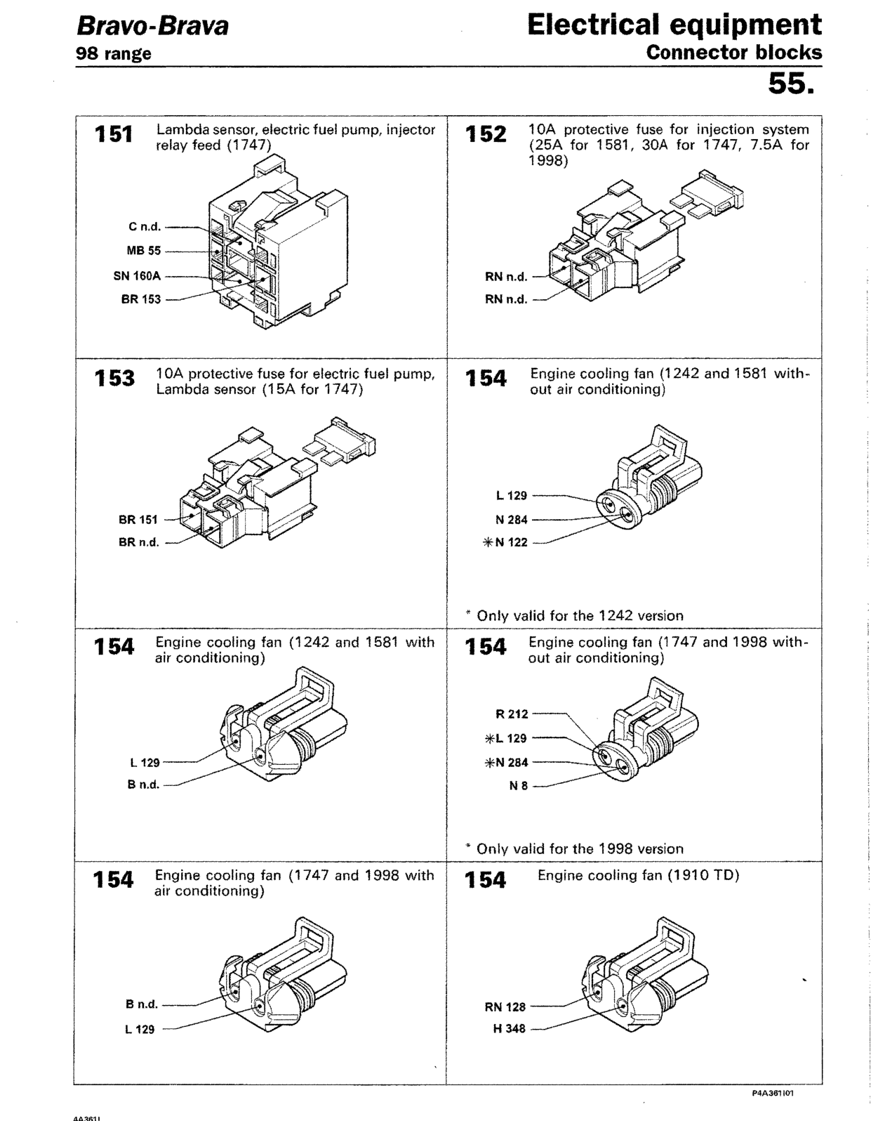
151 Lambda sensor, electric fuel pump, injector relay feed (1747)
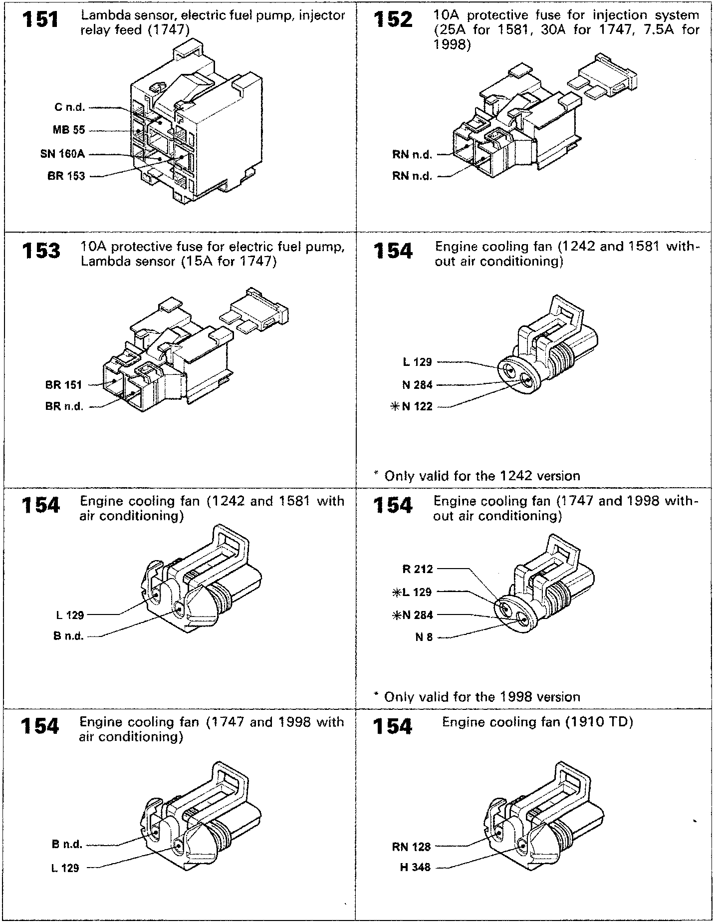
152 10A protective fuse for injection system (25A for 1581, 30A for 1747, 7.5A for 1998)
153 10A protective fuse for electric fuel pump, Lambda sensor (15A for 1747)
154 Engine cooling fan (1242 and 1581 without air conditioning)
* Only valid for the 1242 version
154 Engine cooling fan (1242 and 1581 with air conditioning)
154 Engine cooling fan (1747 and 1998 without air conditioning)
* Only valid for the 1998 version
154 Engine cooling fan (1747 and 1998 with air conditioning)
154 Engine cooling fan (1910 TD)
Original page
Parts & tools for this job For 1995 Fiat Bravo
- TOOLDigital multimeterSearch: automotive digital multimeter
- PARTAssorted fuse kitSearch: car fuse assortment kit
- TOOLWire crimper and connector kitSearch: wire crimper connector kit
Links open Amazon search results in a new tab. As an Amazon Associate I earn from qualifying purchases.