
Control module
- Make
- Fiat
- Model
- Bravo /Brava (182) Factory Service Manual
- Year
- 1995–2001
- Section
- Control units (98 range) › Control module
‹ Prev Wiring diagram for PETROL version, SX, ELX (1581 with AUTOMATIC TRANSMISSION)Next › Connector B on facia lead
55 Electrical systemControl module
Control module
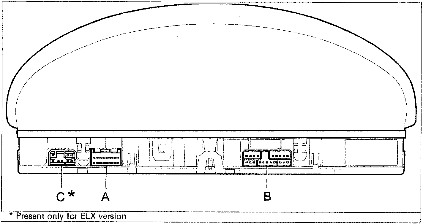
* Present only for ELX version
Rear side (connector sockets are shown)
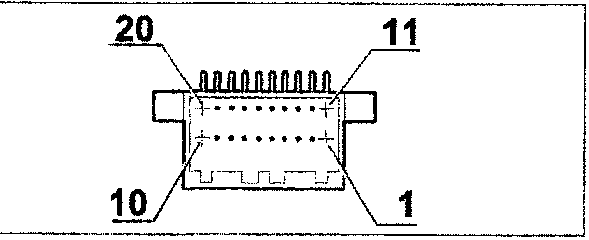
Connector A on left front lead
| No. pin | Wiring Colour | Circuit involved |
|---|---|---|
| 1 | HN | Generator |
| 2 | BN | Brake fluid level |
| 3 | LN | Injection failure |
| 4 | R | +30 battery |
| 5 | - | Not connected |
| 6 | - | Not connected |
| 7 | - | Not connected |
| 8 | BR | Brake lining wear |
| 9 | MN | Fiat CODE |
| 10 | - | Not connected |
| 11 | - | Not connected |
| 12 | HG | Insufficient engine oil pressure |
| 13 | HM | Speedometer signal |
| 14 | - | Not connected |
| 15 | CN | Speedometer generator power supply |
| 16 | L | Rev counter signal |
| 17 | HB | Engine coolant temperature |
| 18 | - | Not connected |
| 19 | RV | ABS system failure |
| 20 | - | Not connected |
‹ Prev Wiring diagram for PETROL version, SX, ELX (1581 with AUTOMATIC TRANSMISSION)Next › Connector B on facia lead
Parts & tools for this job For 1995 Fiat Bravo
- TOOLOBD2 scannerSearch: OBD2 scanner
- TOOLDigital multimeterSearch: automotive digital multimeter
- TOOLBack-probe test leadsSearch: back probe test leads
Links open Amazon search results in a new tab. As an Amazon Associate I earn from qualifying purchases.