
Removing-refitting
- Make
- Fiat
- Model
- Bravo /Brava (182) Factory Service Manual
- Year
- 1995–2001
- Section
- Instrument panel (99 range) › Removing-refitting
55 Electrical systemRemoving-refitting
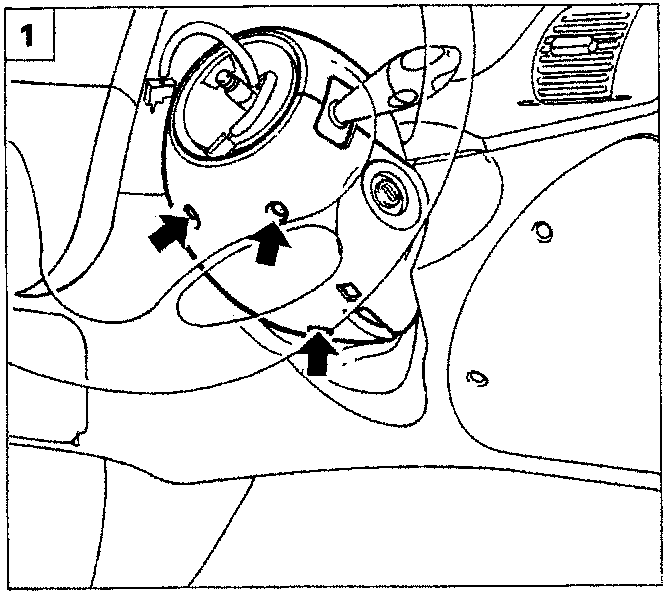
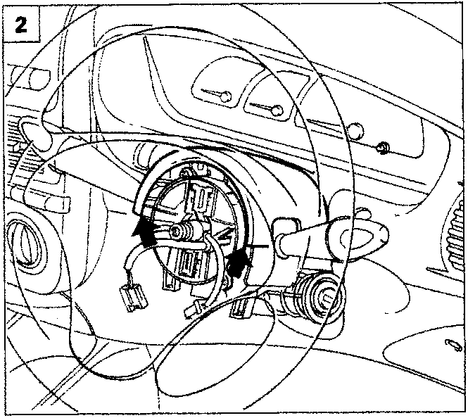
REMOVING-REFITTING
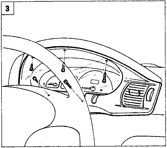
- Disconnect the battery negative terminal, then remove the lower steering column trim by undoing the bolts indicated in the figure.
- Remove the upper steering column trim in order to allow removal of the lower control panel frame screws.
- Unscrew the bolts fastening the outside of the control panel frame.
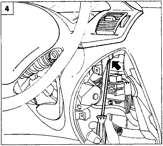
- Remove the junction unit protective cover. Unscrew the outer control panel frame retaining screw. Remove the frame from the facia and disconnect the lighting dimmer and headlamp beam alignment connectors.
Parts & tools for this job For 1995 Fiat Bravo
- TOOLDigital multimeterSearch: automotive digital multimeter
- PARTAssorted fuse kitSearch: car fuse assortment kit
- TOOLWire crimper and connector kitSearch: wire crimper connector kit
Links open Amazon search results in a new tab. As an Amazon Associate I earn from qualifying purchases.