
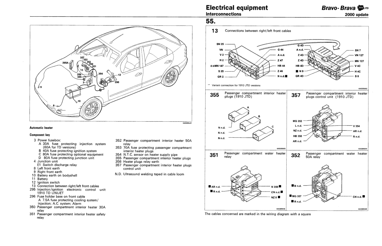
Location of components - Automatic heater
- Make
- Fiat
- Model
- Bravo /Brava (182) Factory Service Manual
- Year
- 1995–2001
- Section
- Wiring diagrams (2000 range) › Location of components - Automatic heater
Location of components - Automatic heater
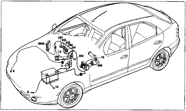
Component key
3 Power fusebox:
A 30A fuse protecting injection system (60A for TD versions)
B 40A fuse protecting ignition system
C 80A fuse protecting optional equipment
D 80A fuse protecting junction unit
4 Junction unit
E1 Switch discharge relay
8 Left front earth
9 Right front earth
10 Battery earth on bodyshell
11 Battery
12 Ignition switch
13 Connection between right/left front cables
295 Injection/ignition electronic control unit 1910 TD UNIJET
296 Fuse holder base on front cable
A 7.5A fuse protecting cooling system/injection; A.C. system; Alarm
350 Passenger compartment interior heater 30A relay
351 Passenger compartment interior heater safety relay
352 Passenger compartment interior heater 50A relay
353 70A fuse protecting passenger compartment interior heater plugs
354 N.T.C. sensor on heater supply pipe
355 Passenger compartment interior heater plugs
356 Heater plugs relay earth
357 Passenger compartment interior heater plugs control unit
N.D. Ultrasound welding taped in cable loom
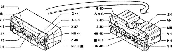
** Variant connection for 1910 JTD versions
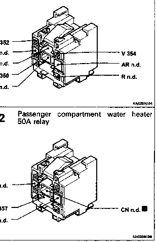
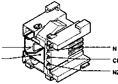
The cables concerned are marked in the wiring diagram with a square
Original page
Parts & tools for this job For 1995 Fiat Bravo
- TOOLA/C manifold gauge setSearch: AC manifold gauge set
- TOOLUV leak detection kitSearch: AC UV leak detection kit
- PARTCabin filterSearch: Fiat Bravo 1995 cabin filter
Links open Amazon search results in a new tab. As an Amazon Associate I earn from qualifying purchases.