
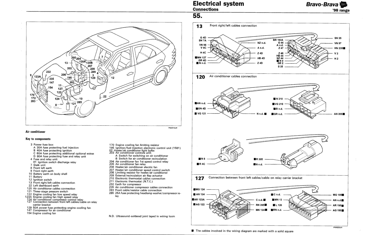
Air conditioner
- Make
- Fiat
- Model
- Bravo /Brava (182) Factory Service Manual
- Year
- 1995–2001
- Section
- Wiring diagrams (98 range) › Air conditioner
55 Electrical systemAir conditioner
Air conditioner
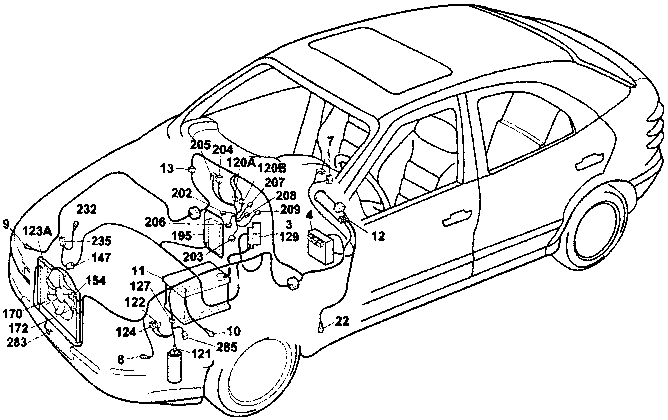
Key to components
| 3 Power fuse box: | |
| A 30A fuse protecting fuel injection | |
| B 40A fuse protecting ignition | |
| C 60A fuse protecting additional optional extras | |
| D 80A fuse protecting fuse and relay unit | |
| 4 Fuse and relay unit: | |
| E1 Ignition switch discharge relay | |
| 7 Stalk unit | |
| 8 Front left earth | |
| 9 Front right earth | |
| 10 Battery earth on body shell | |
| 11 Battery | |
| 12 Ignition switch | |
| 13 Front right/left cables connection | |
| 22 Left dashboard earth | |
| 120 Air conditioner cables connection | |
| 121 Three-stage pressure switch | |
| 122 Engine cooling fan low speed relay | |
| 123A Engine cooling fan high speed relay | |
| 124 Air conditioner compressor control relay | |
| 127 Connection between front left cables/cable on relay carrier bracket | |
| 129 50A power fuse protecting engine cooling fan | |
| 147 Compressor for air conditioner | |
| 154 Engine cooling fan | |
| 170 Engine cooling fan limiting resistor | |
| 195 Ignition/fuel injection electronic control unit (1581) | |
| 02 Heater/air conditioner light bulbs | |
| 203 Air conditioner controls unit: | |
| A Switch for switching on air conditioner | |
| B Switch for air conditioner recirculation | |
| 204 Air conditioner fan 1st speed control relay | |
| 205 Air conditioner fan relay | |
| 206 Heater/air conditioner electric fan | |
| 207 Heater/air conditioner speed control switch | |
| 208 Limiting resistor for heater/air conditioner | |
| 209 External/recirculation air flap actuator | |
| 210 Electronic thermostat cables connection | |
| 211 Electronic thermostat (N.T.C.) | |
| 232 Earth for compressor | |
| 235 Air conditioner compressor cables connection | |
| 283 Front cable/resistor cable connection | |
| 285 25A fuse protecting headlamp washer/compressor relay |
N.D. Ultrasound-soldered joint taped in wiring loom
13 Front right/left cables connection
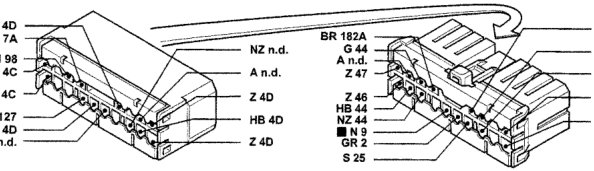
120 Air conditioner cables connection
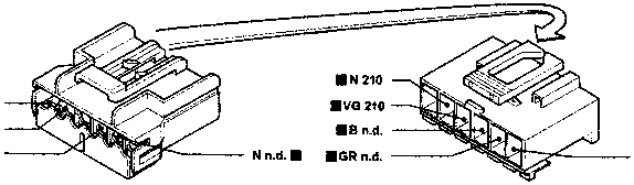
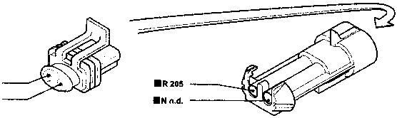
127 Connection between front left cables/cable on relay carrier bracket
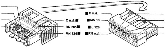
■ The cables involved in the wiring diagram are marked with a solid square
Original page
Parts & tools for this job For 1995 Fiat Bravo
- TOOLDigital multimeterSearch: automotive digital multimeter
- PARTAssorted fuse kitSearch: car fuse assortment kit
- TOOLWire crimper and connector kitSearch: wire crimper connector kit
Links open Amazon search results in a new tab. As an Amazon Associate I earn from qualifying purchases.