
Location of components - Automatic heater
- Make
- Fiat
- Model
- Bravo /Brava (182) Factory Service Manual
- Year
- 1995–2001
- Section
- Wiring diagrams (98 range) › Location of components - Automatic heater
55 Electrical systemLocation of components - Automatic heater
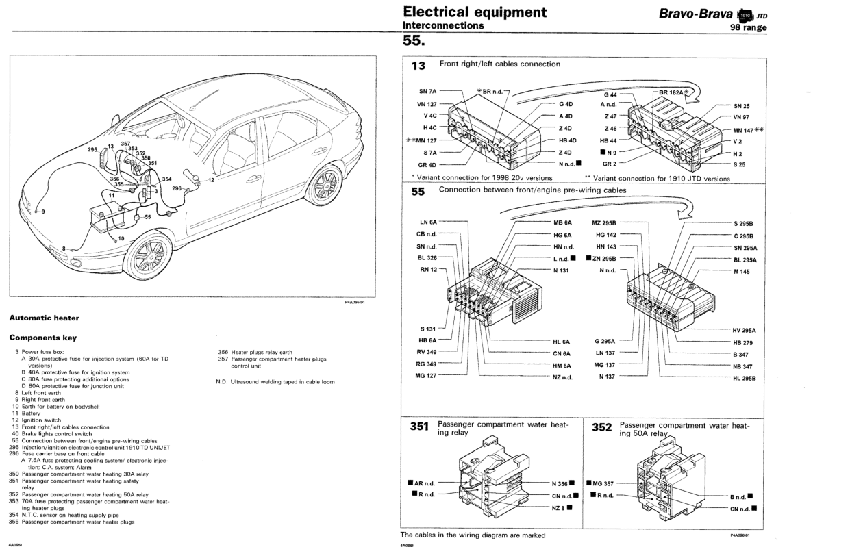
Location of components - Automatic heater
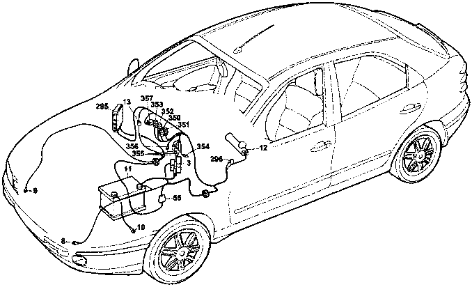
PAA096001
Components key
- 3 Power fuse box:
- A 30A protective fuse for injection system (60A for TD versions)
- B 40A protective fuse for ignition system
- C 80A fuse protecting additional options
- D 80A protective fuse for junction unit
- 8 Left front earth
- 9 Right front earth
- 10 Earth for battery on bodyshe11
- 11 Battery
- 12 Ignition switch
- 13 Front right/left cables connection
- 40 Brake lights control switch
- 55 Connection between front/engine pre-wiring cables
- 295 Injection/ignition electronic control unit 1910 TD UNIJET
- 296 Fuse carrier base on front cable
- A 7.5A fuse protecting cooling system/ electronic injection; C.A. system; Alarm
- 350 Passenger compartment water heating 30A relay
- 351 Passenger compartment water heating safety relay
- 352 Passenger compartment water heating 50A relay
- 353 70A fuse protecting passenger compartment water heating heater plugs
- 354 N.T.C. sensor on heating supply pipe
- 355 Passenger compartment water heater plugs
- 356 Heater plugs relay earth
- 357 Passenger compartment heater plugs control unit
- N.D. Ultrasound welding taped in cable loom
13 Front right/left cables connection
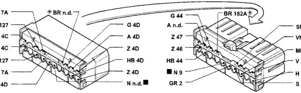
* Variant connection for 1998 20v versions ** Variant connection for 1910 JTD versions
55 Connection between front/engine pre-wiring cables
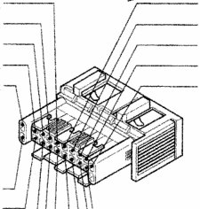
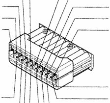
351 Passenger compartment water heating 30A relay
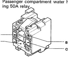
352 Passenger compartment water heating 50A relay
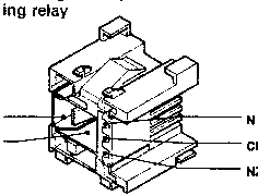
The cables in the wiring diagram are marked
PAA096001
Original page
Parts & tools for this job For 1995 Fiat Bravo
- TOOLA/C manifold gauge setSearch: AC manifold gauge set
- TOOLUV leak detection kitSearch: AC UV leak detection kit
- PARTCabin filterSearch: Fiat Bravo 1995 cabin filter
Links open Amazon search results in a new tab. As an Amazon Associate I earn from qualifying purchases.