
Connections
- Make
- Fiat
- Model
- Bravo /Brava (182) Factory Service Manual
- Year
- 1995–2001
- Section
- Wiring diagrams (98 range, 1910 JTD) › Connections
Connections
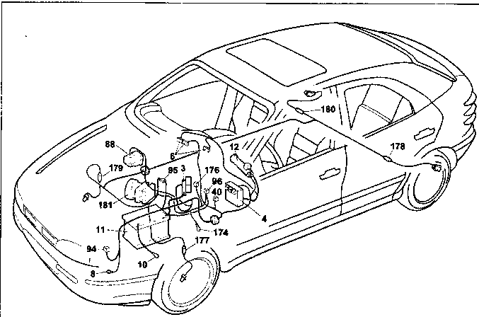
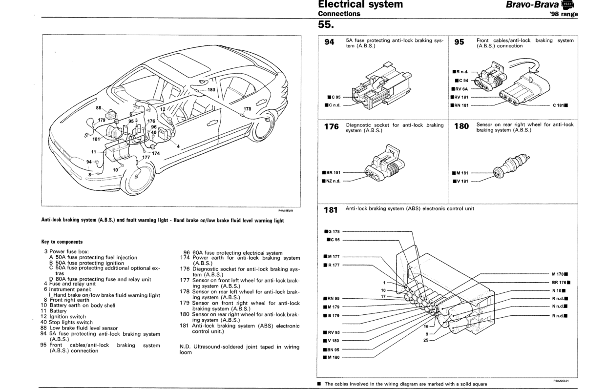
Anti-lock braking system (A.B.S.) and fault warning light - Hand brake on/low brake fluid level warning light
Key to components
3 Power fuse box:
A 50A fuse protecting fuel injection
B 50A fuse protecting ignition
C 50A fuse protecting additional optional extras
D 80A fuse protecting fuse and relay unit
4 Fuse and relay unit
6 Instrument panel:
I Hand brake on/low brake fluid warning light
8 Front right earth
10 Battery earth on body shell
11 Battery
12 Ignition switch
40 Stop lights switch
88 Low brake fluid level sensor
94 5A fuse protecting anti-lock braking system (A.B.S.)
95 Front cables/anti-lock braking system (A.B.S.) connection
96 60A fuse protecting electrical system
174 Power earth for anti-lock braking system (A.B.S.)
176 Diagnostic socket for anti-lock braking system (A.B.S.)
177 Sensor on front left wheel for anti-lock braking system (A.B.S.)
178 Sensor on rear left wheel for anti-lock braking system (A.B.S.)
179 Sensor on front right wheel for anti-lock braking system (A.B.S.)
180 Sensor on rear right wheel for anti-lock braking system (A.B.S.)
181 Anti-lock braking system (ABS) electronic control unit.
N.D. Ultrasound-soldered joint taped in wiring loom
|
94 5A fuse protecting anti-lock braking system (A.B.S.) 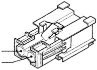
|
95 Front cables/anti-lock braking system (A.B.S.) connection
|
|
176 Diagnostic socket for anti-lock braking system (A.B.S.) 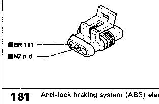
|
180 Sensor on rear right wheel for anti-lock braking system (A.B.S.)
|
|
181 Anti-lock braking system (ABS) electronic control unit 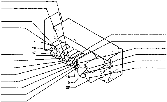
|
|
■ The cables involved in the wiring diagram are marked with a solid square
Original page
Parts & tools for this job For 1995 Fiat Bravo
- TOOLDigital multimeterSearch: automotive digital multimeter
- PARTAssorted fuse kitSearch: car fuse assortment kit
- TOOLWire crimper and connector kitSearch: wire crimper connector kit
Links open Amazon search results in a new tab. As an Amazon Associate I earn from qualifying purchases.