
Variations in pre-heating period
- Make
- Fiat
- Model
- Panda (141) Factory Service Manual
- Year
- 1986–2003
- Section
- Pre-heating (Panda D) › Variations in pre-heating period
55 Electrical systemVariations in pre-heating period
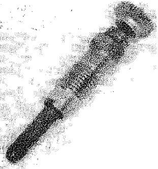
Rapid type heater plug
NOTE The heater plug reaches a temperature of 850°C. It contains a resistive spiral in Alferon which has a high resistance and Nickel which has a low resistance, welded by laser. The outer casing is made of metal.
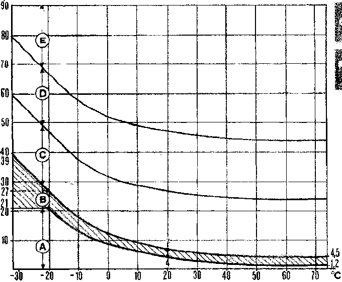
Variations in pre-heating period
- A. Period with heater plugs warning light on.
- B. Range in which the warning light goes out and pre-heating is taking place (shaded area).
- C. Period in which pre-heating is taking place and warning light is off. This stage which lasts 15 - 20 secs is counted starting when the warning light goes out.
- D. Post-heating period with heater plugs on and warning light off. This stage which lasts 15 - 20 secs is counted from when the starting stage is over and the engine is running.
- E. Period with warning light off and pre-heating over.
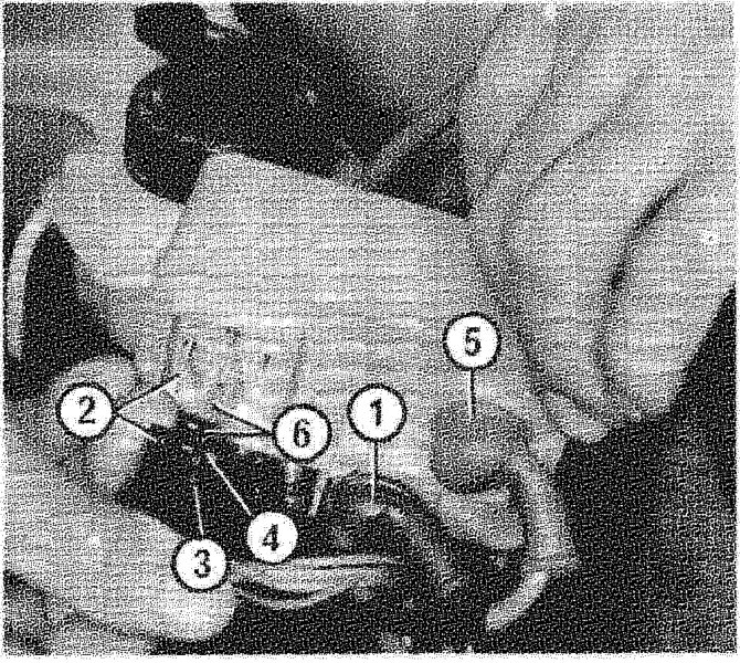
HEATER PLUGS CONTROL UNIT
This is an electronic device which controls a relay for the current to pass automatically between terminals 1 and 5.
The control unit is rendered operational by the following connections:
- 1. large section black cable, from the battery
- 2. black earth cable
- 3. twin orange supply cable from the control unit: one coming from terminal 15/54 of the ignition switch; the other goes to the engine cut out device on the injection pump
- 4. red/black cable (instant starting control); coming from terminal 50 of the ignition switch
- 5. brown cable: to the heater plugs
- 6. brown cable to the heater plugs warning light (contact 6, connector E) of the instrument panel
Parts & tools for this job For 1986 Fiat Panda
- TOOLA/C manifold gauge setSearch: AC manifold gauge set
- TOOLUV leak detection kitSearch: AC UV leak detection kit
- PARTCabin filterSearch: Fiat Panda 1986 cabin filter
Links open Amazon search results in a new tab. As an Amazon Associate I earn from qualifying purchases.