
Ignition switch assembly - r+r
- Make
- Fiat
- Model
- Ulysse Factory Service Manual
- Year
- 2002–2010
- Section
- Engine starting › Ignition switch assembly - r+r
IGNITION SWITCH ASSEMBLY - R+R
Removing
It is not possible to order key lock barrels on their own or to oder lock barrels with the spares code only. To order lock barrels, follow the special procedure described in operation 5580 - Special Accessories.
Op. 5530B56 BATTERY DRIP TRAY COVER - R.R.
- Disconnect the negative battery terminal.
Op. 7040H29 FRONT PILLAR LOWER COVER (ONE), LEFT OR RIGHT - R.R.
Op. 7040H44 LEFT OR RIGHT REAR PILLAR LOWER TRIM (ONE) - R.R.
Op. 7040A68 GRILLE FOR CENTRE DASHBOARD SPEAKER - R.R.
Op. 7040A47 ODDMENTS POCKET UNDER DASHBOARD - R.R.
Op. 7040A60 UNDER FACIA TRIM - R+R
Before working on the Air Bag system, follow the safety instructions for working on the system very carefully (See 5580C - Air Bag System - Precautions).
Before removing the steering wheel, place the wheels as parallel as possible to the longitudinal axis of the vehicle.
Op. 4110A10 STEERING WHEEL - R+R FOR REPLACEMENT OR CHECKS
Op. 5550A10 STALK UNIT ASSEMBLY - R+R
Op. 4110A26 STEERING WHEEL ADJUSTMENT PLATES - R.R.
Op. 5580E08 AERIAL FOR ALPHA CODE - R R
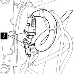
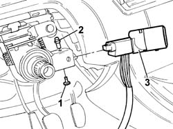
1. Remove the lower bolt.
2. Insert a suitable tool in the bolt housing and extract the upper pin.
3. Remove the ignition switch complete with electrical wiring.
Refitting
- Place the ignition switch in its housing in the steering column.
- Insert the upper pin.
- Tighten a new bolt.
- Connect the electrical connections.
- Secure the wiring suitably.
Op. 5580E08 AERIAL FOR ALPHA CODE - R R
Op. 4110A26 STEERING WHEEL ADJUSTMENT PLATES - R.R.
Op. 5550A10 STALK UNIT ASSEMBLY - R+R
Op. 4110A10 STEERING WHEEL - R+R FOR REPLACEMENT OR CHECKS
Op. 5580C18 AIR BAG MODULE - R+R
Op. 7040A26 STEERING COLUMN TRIM - R+R
Op. 7040A60 UNDER FACIA TRIM - R+R
Op. 7040A47 ODDMENTS POCKET UNDER DASHBOARD - R.R.
Op. 7040A68 GRILLE FOR CENTRE DASHBOARD SPEAKER - R.R.
Op. 7040A44 SEAT INTERIOR GUARD - R R
Op. 7040H29 FRONT PILLAR LOWER COVER (ONE), LEFT OR RIGHT - R.R.
- < R1 > [All]
Parts & tools for this job For 2002 Fiat Ulysse
- TOOLOBD2 scannerSearch: OBD2 scanner
- TOOLDigital multimeterSearch: automotive digital multimeter
- TOOLBack-probe test leadsSearch: back probe test leads
Links open Amazon search results in a new tab. As an Amazon Associate I earn from qualifying purchases.