
System cable bundle - r + r
- Make
- Fiat
- Model
- Ulysse Factory Service Manual
- Year
- 2002–2010
- Section
- Petrol injection system › System cable bundle - r + r
SYSTEM CABLE BUNDLE - R + R
Removing
- Position the vehicle on the lift.
- Disconnect the negative battery terminal.
| Description | Connector | |
|---|---|---|
| Battery | A001B |
Op. 7055B54 UNDER-ENGINE GUARD - R R
Op. 5050B34 WINDSCREEN WIPER ARM/S COMPLETE WITH BLADE - R+R
Op. 5010B18 CLIMATE CONTROL UNIT AIR INTAKE - R.R.
Op. 7210E22 WINDSCREEN BASE TRIM
See in Op. 1088B10
Op. 1016A42 LEFT HAND CYLINDER HEAD IGNITION COIL COVER - R+R
Op. 1048A59 TUBAZIONE DA DEBIMETRO A MANICOTTO CORPO FARFALLATO - S.R.
See in Op. 1068A54
Op. 1072B50 SLEEVES CONNECTING AIR CAPACITY BOX TO INLET MANIFOLD IS - R+R
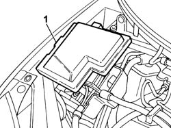
1. Remove the junction unit cover.
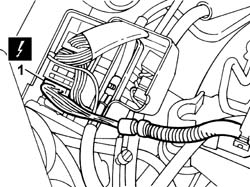
1. Disconnect the engine cable loom electrical connection.
| Description | Connector | |
|---|---|---|
| 1 | Engine compartment junction unit | B001B |
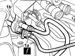
1. Disconnect the electrical connection (1a) ffrom the fuel vapour cut out valve (1b).
| Description | Connector | |
|---|---|---|
| 1a | Fuel vapour recovery solenoid valve | L010 |
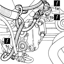
1. Working underneath the vehicle, disconnect the connector (1a) for the engine oil level sensor, disconnect the connector (1b) for the engine oil pressure switch and disconnect the connector (1c) for the air conditioning compressor engagement solenoid.
| Description | Connector | |
|---|---|---|
| 1a | Engine oil level sensor | K032 |
| Description | Connector | |
|---|---|---|
| 1c | Air conditioning compressor engagement electro-magnet | L020 |
| Description | Connector | |
|---|---|---|
| 1b | Engine oil pressure switch | K030 |
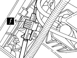
1. Working on the right head, timing side, disconnect the electrical connection for the upper Lambda sensor on the left pre-catalyzer.
| Description | Connector | |
|---|---|---|
| 1 | Lambda sensor on pre-catalyzer | K015 |
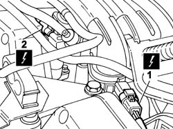
1. Working on the right head, timing side, disconnect the electrical connection from the phase transformer solenoid
| Description | Connector | |
|---|---|---|
| 1 | Swirl solenoid valve | L015 |
2. Working on the left head, timing side, disconnect the electrical connection from the phase transformer solenoid
| Description | Connector | |
|---|---|---|
| 2 | Swirl solenoid valve | L015 |
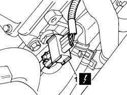
1. Working on the left head, flywheel side, disconnect the electrical connection for the lower Lambda sensor on the left pre-catalyzer.
| Description | Connector | |
|---|---|---|
| 1 | Lambda sensor on catalyzer | K017 |
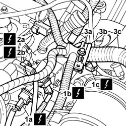
1. Working from the flywheel side, disconnect the electrical connections (1a) for the detonation sensor on the left head (1b), the detonation sensor on the right head and (1c) the engine coolant temperature sensor.
| Description | Connector | |
|---|---|---|
| 1a | Detonation sensor | K050 |
| Description | Connector | |
|---|---|---|
| 1b | Detonation sensor -2 | K051 |
| Description | Connector | |
|---|---|---|
| 1c | Engine coolant temperature sensor/sender unit | K036 |
2. disconnect the electrical connections (2a) for the reference sensor for cylinder 1 on the left head and (2b) the reference sensor for cylinder 2 on the right head.
| Description | Connector | |
|---|---|---|
| 2a | Cylinder reference sensor - 1 | K168 |
| Description | Connector | |
|---|---|---|
| 2b | Cylinder reference sensor -2 | K169 |
3. Undo the fixing bolt (3a) and detach the mounting collar (3b), then move the wiring (3c) aside.
1. Working on the left head, disconnect the electrical connections from the ignition coils.
| Description | Connector | |
|---|---|---|
| 1 | Ignition coil | A030A |
| Description | Connector | |
|---|---|---|
| 1 | Ignition coil | A030C |
| Description | Connector | |
|---|---|---|
| 1 | Ignition coil | A030B |
2. Disconnect the electrical connection joining the coil/injector cables and move the wiring
| Description | Connector | |
|---|---|---|
| 2 | Coil/injector coupling | D080 |
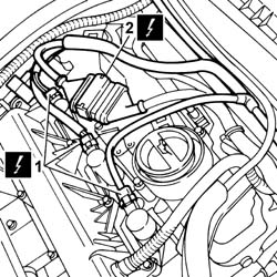
1. Working on the right head, flywheel side, disconnect the electrical connection for the lower Lambda sensor on the left pre-catalyzer.
| Description | Connector | |
|---|---|---|
| 1 | Lambda sensor on catalyzer - 2 | K018 |
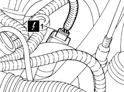
- Working on the right head behind the air intake chamber
1. disconnect the electrical connection for the upper Lambda sensor on the right pre-catalyzer.
| Description | Connector | |
|---|---|---|
| 1 | Lambda sensor on pre-catalyzer - 2 | K016 |
2. Disconnect the electrical connection from the intake air pressure sensor.
| Description | Connector | |
|---|---|---|
| 2 | Air pressure sensor | K082 |
3. Release the wiring from the mountings.
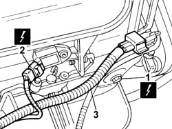
- Working on the right head:
1. Disconnect the electrical connections from the ignition coils.
| Description | Connector | |
|---|---|---|
| 1 | Ignition coil | A030D |
| Description | Connector | |
|---|---|---|
| 1 | Ignition coil | A030F |
| Description | Connector | |
|---|---|---|
| 1 | Ignition coil | A030E |
2. Disconnect the electrical connections from the injectors.
| Description | Connector | |
|---|---|---|
| 2 | Injector | N070D |
| Description | Connector | |
|---|---|---|
| 2 | Injector | N070E |
| Description | Connector | |
|---|---|---|
| 2 | Injector | N070F |
3. Release the cable from the mountings on the tappet cover.
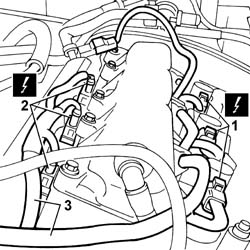
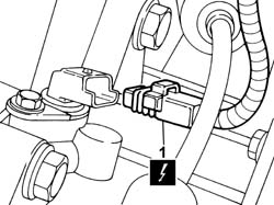
1. Disconnect the electrical connection from the engine rpm sensor located on the bellhousing by the flywheel.
| Description | Connector | |
|---|---|---|
| 1 | Rpm sensor | K046 |
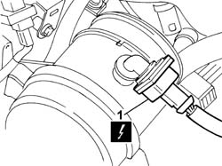
1. Disconnect the electrical connection from the air temperature sensor.
| Description | Connector | |
|---|---|---|
| 1 | Air temperature sensor | K042 |
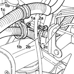
1. Undo the fixing nut (1a), remove the securing bands (1b) and release the wiring (1c).
2. Undo the fixing nut (2a), remove the securing band (2b) and release the wiring (1c).
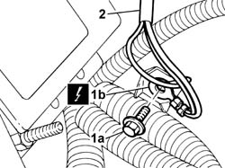
1. Undo the fixing bolt (1a) and detach the wiring earth connection (1b).
| Description | Connector | |
|---|---|---|
| 1b | Left front earth | C010A |
2. Release the wiring from the mountings and move it aside to free up the work area.
1. Undo the retaining bolts (1a) and remove the engine management control unit guard (1b).
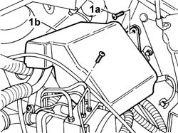
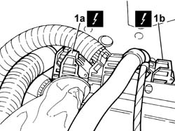
1. Disconnect the electrical connections (1a) and (1b) from the injection/ignition system control unit.
| Description | Connector | |
|---|---|---|
| 1a | Engine management control unit | M010B |
| Description | Connector | |
|---|---|---|
| 1b | Engine management control unit | M010C |
- Remove the engine cable loom from the vehicle.
Refitting
- Place the engine cable loom in the vehicle.
- Connect the electrical connections to the engine management control unit.
| Description | Connector | |
|---|---|---|
| Engine management control unit | M010B |
| Description | Connector | |
|---|---|---|
| Engine management control unit | M010C |
- Position the wiring and fasten the connection to earth
| Description | Connector | |
|---|---|---|
| Left front earth | C010A |
- Position the wiring, fit the securing bands and tighten the fixing nuts.
- Connect the electrical connection to the temperature sensor.
| Description | Connector | |
|---|---|---|
| Air temperature sensor | K042 |
- Connect the electrical connection for the engine rpm sensor.
| Description | Connector | |
|---|---|---|
| Rpm sensor | K046 |
- Connect the electrical connection to the engine coolant temperature sensor.
| Description | Connector | |
|---|---|---|
| Engine coolant temperature sensor/sender unit | K036 |
- Connect the electrical connections to the ignition coils on the right head.
| Description | Connector | |
|---|---|---|
| Ignition coil | A030D |
| Description | Connector | |
|---|---|---|
| Ignition coil | A030E |
| Description | Connector | |
|---|---|---|
| Ignition coil | A030F |
- Connect the electrical connections to the injectors on the right head.
| Description | Connector | |
|---|---|---|
| Injector | N070D |
| Description | Connector | |
|---|---|---|
| Injector | N070E |
| Description | Connector | |
|---|---|---|
| Injector | N070F |
- Secure the cable to the mountings on the tappet cover.
- Working on the right head behind the air intake chamber:
- Connect the electrical connection to the Lambda sensor on the right pre-catalyzer.
| Description | Connector | |
|---|---|---|
| Lambda sensor on pre-catalyzer - 2 | K016 |
- Connect the electrical connection to the intake air pressure sensor.
| Description | Connector | |
|---|---|---|
| Air pressure sensor | K082 |
- Secure the wiring to the mountings.
- Working on the right head, flywheel side:
- Connect the electrical connection for the Lambda sensor on the right pre-catalyzer
| Description | Connector | |
|---|---|---|
| Lambda sensor on catalyzer - 2 | K018 |
- Connect the electrical connections to the ignition coils.
| Description | Connector | |
|---|---|---|
| Ignition coil | A030A |
| Description | Connector | |
|---|---|---|
| Ignition coil | A030C |
| Description | Connector | |
|---|---|---|
| Ignition coil | A030B |
- Connect the electrical connection joining the coil/injector cables and secure the wiring
| Description | Connector | |
|---|---|---|
| Coil/injector coupling | D080 |
- Connect the electrical connection to the reference sensor for cylinder 1 on the left head
| Description | Connector | |
|---|---|---|
| Cylinder reference sensor - 1 | K168 |
- Connect the electrical connection to the reference sensor for cylinder 2 on the right head
| Description | Connector | |
|---|---|---|
| Cylinder reference sensor -2 | K169 |
- Connect the electrical connection to the detonation sensor on the left head
| Description | Connector | |
|---|---|---|
| Detonation sensor | K050 |
- Connect the electrical connection to the detonation sensor on the right head
| Description | Connector | |
|---|---|---|
| Detonation sensor -2 | K051 |
- Position the wiring and tighten the bolt fixing the mounting collar.
- Connect the electrical connection for the Lambda sensor on the left pre-catalyzer.
| Description | Connector | |
|---|---|---|
| Lambda sensor on pre-catalyzer | K015 |
- Position the engine management control unit guard and tighten the fixing bolts.
- Working on the timing side:
- Connect the electrical connection to the phase transformer solenoid on the right head
| Description | Connector | |
|---|---|---|
| Swirl solenoid valve | L015 |
- Connect the electrical connection to the phase transformer solenoid on the left head
| Description | Connector | |
|---|---|---|
| Swirl solenoid valve | L015 |
- Connect the electrical connection for the Lambda sensor on the left pre-catalyzer
| Description | Connector | |
|---|---|---|
| Lambda sensor on catalyzer | K017 |
- Working underneath the vehicle:
- Connect the electrical connection to the engine oil level sensor.
| Description | Connector | |
|---|---|---|
| Engine oil level sensor | K032 |
- Connect the electrical connection to the engine oil pressure switch.
| Description | Connector | |
|---|---|---|
| Engine oil pressure switch | K030 |
- Connect the electrical connection to the air conditioning compressor engagement solenoid.
| Description | Connector | |
|---|---|---|
| Air conditioning compressor engagement electro-magnet | L020 |
- Connect the electrical connection to the fuel vapour cut out valve.
| Description | Connector | |
|---|---|---|
| Fuel vapour recovery solenoid valve | L010 |
- Connect the electrical connection for the engine cable loom to the junction unit in the engine compartment.
| Description | Connector | |
|---|---|---|
| Engine compartment junction unit | B001B |
- Place the cover on the junction unit in the engine compartment.
Op. 1072B50 SLEEVES CONNECTING AIR CAPACITY BOX TO INLET MANIFOLD IS - R+R
See in Op. 1068A54
Op. 1048A59 TUBAZIONE DA DEBIMETRO A MANICOTTO CORPO FARFALLATO - S.R.
Op. 1016A42 LEFT HAND CYLINDER HEAD IGNITION COIL COVER - R+R
See in Op. 1088B10
Op. 7210E22 WINDSCREEN BASE TRIM
Op. 5010B18 CLIMATE CONTROL UNIT AIR INTAKE - R.R.
Op. 5050B34 WINDSCREEN WIPER ARM/S COMPLETE WITH BLADE - R+R
Op. 7055B54 UNDER-ENGINE GUARD - R R
- Connect the negative battery terminal.
| Description | Connector | |
|---|---|---|
| Battery | A001B |
Op. 0010T21 COOLANT CHECK DENSITY AND TOP UP IF NECESSARY
- Remove the vehicle from the lift.
Parts & tools for this job For 2002 Fiat Ulysse
- PARTEngine gasket setSearch: Fiat Ulysse 2002 engine gasket set
- TOOLTorque wrenchSearch: 3/8 inch torque wrench
- TOOLFeeler gauge setSearch: feeler gauge set
Links open Amazon search results in a new tab. As an Amazon Associate I earn from qualifying purchases.