
Alignment: Specifications (page 5 of 5)
- Make
- Ford
- Model
- Aspire
- Engine
- L4-81 1.3L SOHC
- Year
- 1994
- Section
- Alignment
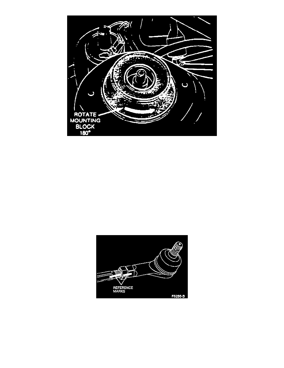
Front Camber Adjustment
Camber
Camber angle is controlled by the position of the strut mounting block in the shock tower. The mounting block can be positioned in the tower in
two ways, resulting in a camber variation of approximately 1/2°. If the camber setting has not been changed previously, the white alignment mark
on the mounting block will be positioned on the outboard side of the strut assembly. Changing the position of the alignment mark 180° will
increase camber angle approximately 1/2°. If the alignment mark is already positioned inboard of the strut, changing the mounting block position
can only result in camber being reduced by approximately 1/2°. To adjust camber setting, proceed as follows:
1. Raise and support vehicle and remove front wheels.
2. Remove upper strut attaching nuts.
3. Lower strut sufficiently so that mounting studs clear tower, then rotate mounting block 180° as necessary.
4. Reposition strut in tower, then install attaching nuts and torque to 32-45 ft lb.
Toe-In
1. Ensure tires are properly inflated, then position vehicle on suitable alignment rack.
2. Bounce vehicle several times to normalize ride height, then check toe setting. If toe setting is not within specification, proceed to next step.
3. Mark relationship between tie rods, tie rod ends and jam nuts, then loosen tie rod boot clamps to prevent twisting or damage to boots.
4. Adjust toe-in by turning both tie rods in or out an equal amount until toe setting is within specification.
5. After adjustment is completed, tighten jam nuts and boot clamps.
REAR WHEEL ALIGNMENT
Rear camber and toe-in are determined by the configuration of the trailing arms on the torsion beam rear axle. No provision for adjustment is
provided. The only rear suspension adjustment possible is the lateral positioning of the rear axle. This adjustment should only be performed if
replacing the rear axle assembly.
Pinch or Ctrl + scroll to zoom. Double-tap to reset.
Parts & tools for this job For 1994 Ford Aspire 1.3L
- TOOLTie rod end toolSearch: tie rod end puller
- TOOLBall joint separatorSearch: ball joint separator
- FLUIDPower steering fluidSearch: Ford power steering fluid
Links open Amazon search results in a new tab. As an Amazon Associate I earn from qualifying purchases.