
Bronco L6-300 4.9L VIN Y 1-bbl (1983)
5.
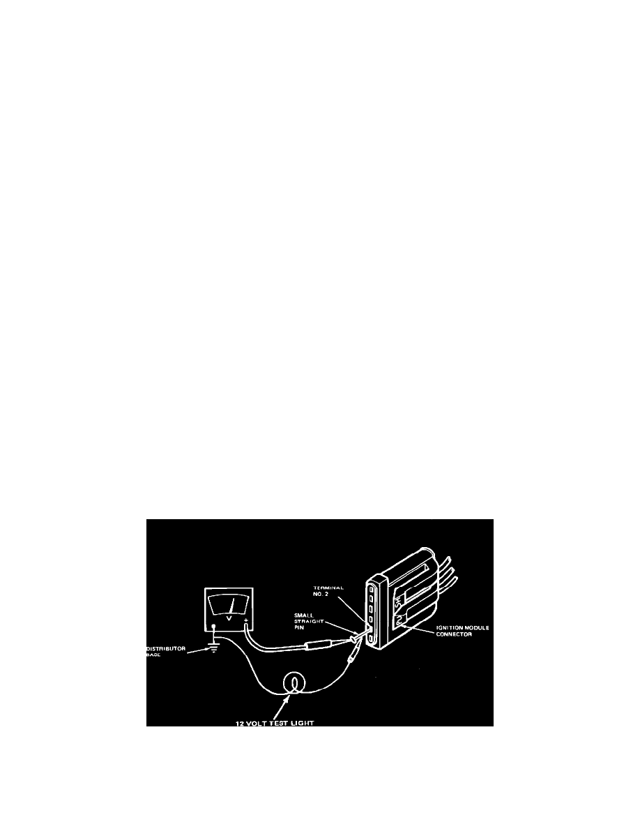
Following table below, measure connector terminal voltage by attaching VOM to small straight pin inserted into connector terminal and turning
ignition switch to position shown.
CAUTION: Do not allow straight pin to contact electrical ground.
CONNECTOR
IGNITION SWITCH
TERMINAL
WIRE/CIRCUIT
TEST POSITION
#2
TO IGNITION
RUN
COIL (-) TERMINAL
#3
RUN CIRCUIT
RUN AND START
#4
START CIRCUIT
START
6.
Turn ignition switch to Off position.
7.
Remove straight pin.
8.
Reconnect wire to S terminal of starter relay.
TEST RESULT
TEST RESOLUTION
90 percent of
^ Test result OK.
battery
^ Go to Part 2, Test 6.
voltage minimum
Less than 90
^ Inspect for faults in wiring
percent of
harness and connectors.
battery
^ Refer to vehicle wiring
voltage
diagram for appropriate
circuit.
^
Damaged or worn ignition switch, Refer to Shop Manual, Group 33.
Primary Circuit Continuity
TFI-IV
Part 2
Test 8
TEST EQUIPMENT: VOM, STRAIGHT PIN
TEST PROCEDURE
1.
Separate wiring harness connector from ignition module. Inspect for dirt, corrosion, and damage.
NOTE:
PUSH connector tabs to separate.