
Bronco L6-300 4.9L VIN Y 1-bbl (1983)
Stator: Testing and Inspection
Fig. 13 Testing diode trio
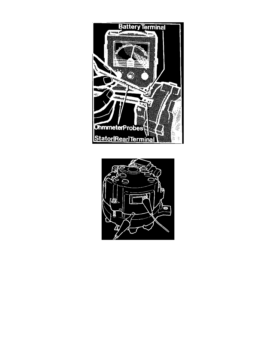
Fig. 14 Alternator w/integral regulator rectifier short or grounded & stator grounded test
RECTIFIER SHORT OR GROUNDED & STATOR GROUNDED TEST
Using a suitable ohmmeter, connect one probe to the alternator BAT terminal, Figs. 13 and 14, and the other probe to the STA terminal (rear blade
terminal). Then, reverse the ohmmeter probes and repeat the test. A reading of about 6.5 ohms should be obtained in one direction and no needle
movement with the probes reversed. A reading in both directions indicates a bad positive diode, a grounded positive diode plate or a grounded BAT
terminal.
Perform the same test using the STA and GND (ground) terminals of the alternator. A reading in both directions indicates either a bad negative diode,
a grounded stator winding, a grounded stator terminal, a grounded positive diode plate, or a grounded BAT terminal.
Infinite readings (no needle movement) in all four probe positions in the preceding tests indicates an open STA terminal lead connection inside the
alternator.