
Bronco Full Size V8-302 5.0L (1986)
Intake Manifold: Service and Repair
Fuel Charging Assembly, Replace
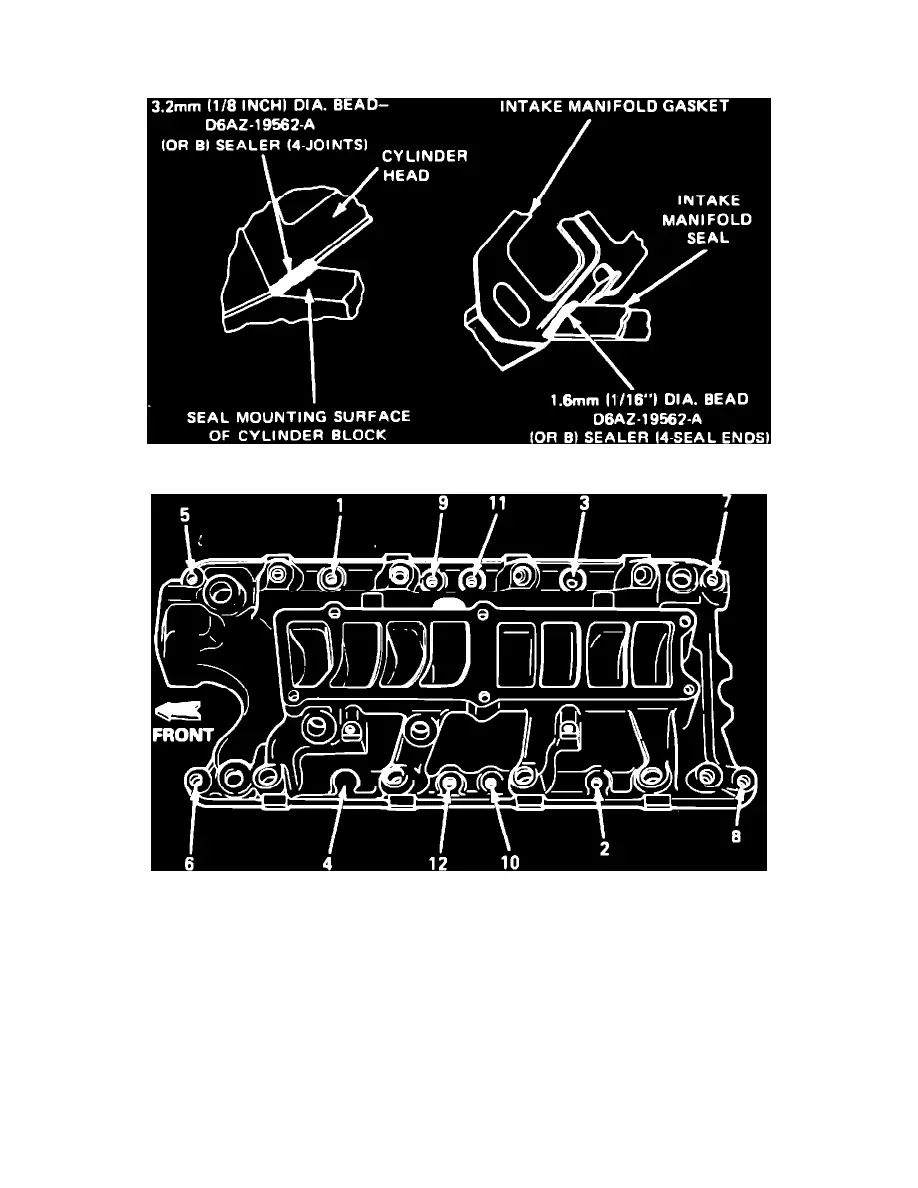
Fig. 18 Applying RTV sealer for intake manifold installation. V8-302 engine
Fig. 19 Lower intake manifold bolt tightening sequence. V8-302 engine
V8-302 Engine
1.
Disconnect battery ground cable.
2.
Disconnect air bypass valve, throttle position sensor and EGR position sensor electrical connector.
3.
Disconnect throttle linkage at throttle ball and automatic overdrive transmission linkage from throttle body.
4.
Remove throttle linkage bracket attaching bolts, then position bracket with cables to one side.
5.
Disconnect upper intake manifold vacuum lines from vacuum tree, then the vacuum lines from EGR valve and fuel pressure regulator.
6.
Disconnect PCV system hose from fitting on rear of upper manifold.
7.
Remove two canister purge lines from throttle body.
8.
On 1986 models, disconnect water heater lines from throttle body.
9.
On all models, disconnect EGR tube from EGR valve.
10.
Remove upper intake manifold attaching bolts, then the upper intake manifold and throttle body as an assembly.
11.
Remove distributor assembly, cap and wires. Mark position of distributor and rotor prior to removal so they can be installed in their original