| Diagnosis and Testing Refer to Wiring Diagrams Section 303-06, for schematic and connector information. Inspection and Verification - Verify the customer concern.
- Visually inspect for obvious signs of mechanical or electrical damage.
Visual Inspection Chart | Mechanical | Electrical | | | - Fuse(s)
- Battery
- Starter relay
- Start inhibit relay
- Wiring harness(es)
- Loose or corroded connector(s)
| - If an obvious cause for an observed or reported concern is found, correct the cause (if possible) before proceeding to the next step.
- If the cause is not visually evident, verify the symptom and refer to the Symptom Chart.
Symptom Chart Symptom Chart | Symptom | Possible Sources | Action | | The engine does not crank and the relay does not click | * Battery * Starter motor * Starter relay * Start inhibit relay * Battery junction box (BJB) * Powertrain control module (PCM) * Circuit(s) | * | | The engine does not crank but the relay clicks | * Battery * Starter relay * Circuit(s) * Starter motor * Ignition switch | * | | The engine cranks slowly | * Battery * Circuit(s) * Starter motor | * | | Unusual starter motor noise | * Starter motor * Flywheel ring gear | * CHECK the flywheel ring gear. * INSPECT the starter motor for alignment or cracked casing. Make sure the mounting bolts are tightened. If necessary, INSTALL a new starter motor.
REFER to: Starter Motor - 1.6L Duratec-16V (Sigma) (303-06 Starting System, Removal and Installation) /
Starter Motor - 1.8L Duratec-HE (MI4)/2.0L Duratec-HE (MI4) (303-06 Starting System, Removal and Installation) /
Starter Motor - 1.6L Duratorq-TDCi (DV) Diesel (303-06 Starting System, Removal and Installation) /
Starter Motor - 1.8L Duratorq-TDCi (Kent) Diesel (303-06 Starting System, Removal and Installation).
TEST the system for normal operation. | | The starter spins but the engine does not crank | * Starter motor * Flywheel ring gear | * INSPECT the flywheel ring gear for missing teeth.
REFER to: Flywheel Inspection (303-00 Engine System - General Information, General Procedures).
CHECK the starter motor for correct mounting. If the concern persists, INSTALL a new starter motor.
REFER to: Starter Motor - 1.6L Duratec-16V (Sigma) (303-06 Starting System, Removal and Installation) /
Starter Motor - 1.8L Duratec-HE (MI4)/2.0L Duratec-HE (MI4) (303-06 Starting System, Removal and Installation) /
Starter Motor - 1.6L Duratorq-TDCi (DV) Diesel (303-06 Starting System, Removal and Installation) /
Starter Motor - 1.8L Duratorq-TDCi (Kent) Diesel (303-06 Starting System, Removal and Installation).
TEST the system for normal operation. | Pinpoint Tests | PINPOINT TEST A : THE ENGINE DOES NOT CRANK AND THE RELAY DOES NOT CLICK | | TEST CONDITIONS | DETAILS/RESULTS/ACTIONS | | A1: CHECK THE BATTERY | | | 1 CHECK the battery voltage using WDS. | | | Is the battery OK? Yes Vehicles with automatic transaxle. GO to A2. No CHARGE the battery.
REFER to: Battery Charging (414-00, General Procedures).
TEST the system for normal operation. If the concern persists, INSTALL a new battery.
REFER to: Battery - 1.6L Duratorq-TDCi (DV) Diesel/2.0L Duratorq-TDCi (DW) Diesel (414-01, Removal and Installation).
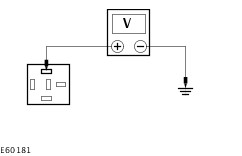
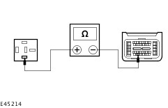
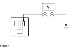
| | A2: CHECK THE STARTER RELAY FOR VOLTAGE | | | 1 Disconnect Starter Relay C1013. | | | 2 Ignition switch in position III. | | | 3 Measure the voltage between the starter relay C1013 pin 1, circuit 50-BB16C (GY/BK), harness side and ground. | | | Is the voltage greater than 10 volts? Yes No | | A3: CHECK THE STARTER RELAY | | | 1 Ignition switch in position 0. | | | 2 Carry out the relay component test on starter relay C1013. For additional information, REFER to the Wiring Diagrams. | | | Does the starter relay pass the component test? Yes Vehicles with 1.8L or 2.0L engine. GO to A5. Vehicles with 1.6L diesel engine. GO to A6. Vehicles with 2.0L diesel engine. GO to A7. Vehicles with 1.8L diesel engine. GO to A7. No INSTALL a new starter relay. TEST the system for normal operation. | | A4: CHECK CIRCUIT 31S-BB16 (BK/RD) FOR OPEN | | | 1 Disconnect PCM C594. | | | 2 Measure the resistance between the starter relay C1013 pin 2, circuit 31S-BB16 (BK/RD), harness side and PCM C594 pin F30, circuit 31S-BB16 (BK/RD), harness side. | | | Is the resistance less than 5 ohms? Yes INSTALL a new PCM.
REFER to: Powertrain Control Module (PCM) - 1.6L Duratec-16V (Sigma) (303-14, Removal and Installation).
TEST the system for normal operation. No REPAIR the circuit. TEST the system for normal operation. | | A5: CHECK CIRCUIT 31S-BB16 (BK/RD) FOR OPEN | | | 1 Disconnect PCM C690. | | | 2 Measure the resistance between the starter relay C1013 pin 2, circuit 31S-BB16 (BK/RD), harness side and PCM C690 pin 4, circuit 31S-BB16 (BK/RD), harness side. | | | Is the resistance less than 5 ohms? Yes INSTALL a new PCM.
REFER to: Powertrain Control Module (PCM) - Vehicles Without: PCM Security Shield (303-14, Removal and Installation) /
Powertrain Control Module (PCM) - Vehicles With: PCM Security Shield (303-14, Removal and Installation).
TEST the system for normal operation. No REPAIR the circuit. TEST the system for normal operation. | | A6: CHECK CIRCUIT 31S-BB16 (BK/RD) FOR OPEN | | | 1 Disconnect PCM C419. | | | 2 Measure the resistance between the starter relay C1013 pin 2, circuit 31S-BB16 (BK/RD), harness side and PCM C419 pin A1, circuit 31S-BB16 (BK/RD), harness side. | | | Is the resistance less than 5 ohms? Yes INSTALL a new PCM.
REFER to: Powertrain Control Module (PCM) - 1.6L Duratorq-TDCi (DV) Diesel/2.0L Duratorq-TDCi (DW) Diesel (303-14, Removal and Installation).
TEST the system for normal operation. No REPAIR the circuit. TEST the system for normal operation. | | A7: CHECK CIRCUIT 31S-BB16 (BK/RD) FOR OPEN | | | 1 Disconnect PCM C418. | | | 2 Measure the resistance between the starter relay C1013 pin 2, circuit 31S-BB16 (BK/RD), harness side and PCM C418 pin D1, circuit 31S-BB16 (BK/RD), harness side. | | | Is the resistance less than 5 ohms? Yes INSTALL a new PCM.
REFER to: Powertrain Control Module (PCM) - 1.6L Duratorq-TDCi (DV) Diesel/2.0L Duratorq-TDCi (DW) Diesel (303-14, Removal and Installation).
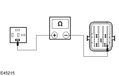
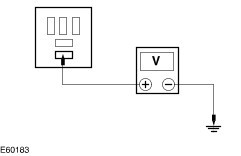
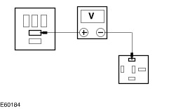
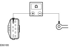
TEST the system for normal operation. No REPAIR the circuit. TEST the system for normal operation. | | A8: CHECK CIRCUIT 15-BB16 (GN/OG) FOR VOLTAGE | | | 1 Ignition switch in position 0. | | | 2 Disconnect Start inhibit relay C1001. | | | 3 Ignition switch in position II. | | | 4 Measure the voltage between the start inhibit relay C1001 pin 1, circuit 15-BB16 (GN/OG), harness side and ground. | | | Is the voltage greater than 10 volts? Yes No REPAIR the circuit. TEST the system for normal operation. | | A9: CHECK CIRCUIT 50-BB16A (GY/BK) FOR VOLTAGE | | | 1 Ignition switch in position III. | | | 2 Measure the voltage between the start inhibit relay C1001 pin 3, circuit 50-BB16A (GY/BK), harness side and ground. | | | Is the voltage greater than 10 volts? Yes No REPAIR the circuit. TEST the system for normal operation. | | A10: CHECK CIRCUIT 31S-TA36 (BK/GN) FOR OPEN | | | 1 Ignition switch in position 0. | | | 2 Disconnect Transmission control unit C812. | | | 3 Measure the resistance between the start inhibit relay C1001 pin 2, circuit 31S-TA36 (BK/GN), harness side and the transmission control unit C812 pin 10, circuit 31S-TA36 (BK/GN), harness side. | | | Is the resistance less than 5 ohms? Yes No REPAIR the circuit. TEST the system for normal operation. | | A11: CHECK THE START INHIBIT RELAY | | | 1 Carry out the relay component test on start inhibit relay C1001. For additional information, REFER to Wiring Diagrams. | | | Does the start inhibit relay pass the component test? Yes No INSTALL a new start inhibit relay. TEST the system for normal operation. | | A12: CHECK CIRCUIT 50-BB16A (GY/BK) FOR OPEN | | | 1 Measure the resistance between the start inhibit relay C1001 pin 5, circuit 50-BB16A (GY/BK), harness side and the starter relay C1013 pin 1, circuit 50-BB16C (GY/BK), harness side. | | | Is the resistance less than 5 ohms? Yes INSTALL a new transmission control unit. TEST the system for normal operation. No REPAIR the circuit. TEST the system for normal operation. | | A13: CHECK THE STARTER RELAY FOR VOLTAGE | | | 1 Disconnect Starter relay C1013. | | | 2 Ignition switch in position III. | | | 3 Measure the voltage between the starter relay C1013 pin 1, circuit 50-BB16 (GY/BK), harness side and ground. | | | Is the voltage greater than 10 volts? Yes No REPAIR circuit 50-BB16 (GY/BK). TEST the system for normal operation. | | PINPOINT TEST B : THE ENGINE DOES NOT CRANK AND THE RELAY CLICKS | | TEST CONDITIONS | DETAILS/RESULTS/ACTIONS | | B1: CHECK THE STARTER MOTOR FOR SWITCHED VOLTAGE | | | 1 Disconnect Starter Motor C110B. | | | 2 Ignition switch in position III. | | | 3 Measure the voltage between the starter motor C110B, circuit 50-BB12 (GY), harness side and ground. | | | Is the voltage greater than 10 volts? Yes No Vehicles with manual transaxle. GO to A3. Vehicle with automatic transaxle. GO to B3. | | B2: CHECK THE STARTER MOTOR FOR BATTERY VOLTAGE | | | 1 Connect Starter Motor C110B. | | | 2 Disconnect Starter Motor 110A. | | | 3 Measure the voltage between the starter motor C110A, circuit 30-BB10 (RD), harness side and ground. | | | Is the voltage greater than 10 volts? Yes INSTALL a new starter motor.
REFER to: Starter Motor - 1.6L Duratec-16V (Sigma) (303-06 Starting System, Removal and Installation) /
Starter Motor - 1.8L Duratec-HE (MI4)/2.0L Duratec-HE (MI4) (303-06 Starting System, Removal and Installation) /
Starter Motor - 1.6L Duratorq-TDCi (DV) Diesel (303-06 Starting System, Removal and Installation) /
Starter Motor - 1.8L Duratorq-TDCi (Kent) Diesel (303-06 Starting System, Removal and Installation).
TEST the system for normal operation. No CLEAN and TIGHTEN all positive battery cable connections. TEST the system for normal operation. If the concern persists. INSTALL a new battery to starter motor cable.
REFER to: Battery Cables - 1.6L Duratec-16V (Sigma) (414-01 Battery, Mounting and Cables, Removal and Installation) /
Battery Cables - 1.8L Duratec-HE (MI4)/2.0L Duratec-HE (MI4) (414-01 Battery, Mounting and Cables, Removal and Installation) /
Battery Cables - 1.6L Duratorq-TDCi (DV) Diesel (414-01 Battery, Mounting and Cables, Removal and Installation) /
Battery Cables - 2.0L Duratorq-TDCi (DW) Diesel (414-01 Battery, Mounting and Cables, Removal and Installation).
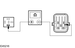
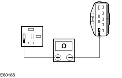
TEST the system for normal operation. | | B3: CHECK CIRCUIT 50-BB12 (GY) FOR OPEN | | | 1 Disconnect Gearshift Mode Switch C438. | | | 2 Measure the resistance between the gearshift mode switch C438 pin 9, circuit 50-BB12 (GY), harness side and the starter motor C110B, circuit 50-BB12 (GY), harness side. | | | Is the resistance less than 5 ohms? Yes No REPAIR the circuit. TEST the system for normal operation. | | B4: CHECK CIRCUITS 50-BB12 (GY) AND 50-BB14 (GY/RD) FOR OPEN | | | 1 Disconnect Starter Relay C1013. | | | 2 Measure the resistance between the starter relay C1013 pin 5, circuit 50-BB12 (GY), harness side and the gearshift mode switch C438 pin 6, circuit 50-BB14 (GY/RD), harness side. | | | Is the resistance less than 5 ohms? Yes No REPAIR the circuit(s). TEST the system for normal operation. | | B5: CHECK THE GEARSHIFT MODE SWITCH | | | 1 Select PARK. | | | 2 Measure the resistance between the gearshift mode switch C438 pin 6, component side and the gearshift mode switch C438 pin 9, component side. | | | 3 Select NEUTRAL. | | | 4 Measure the resistance between the gearshift mode switch C438 pin 6, component side and the gearshift mode switch C438 pin 9, component side. | | | Are the resistances 0 ohms? Yes No INSTALL a new gearshift mode switch. TEST the system for normal operation. | | B6: CHECK THE STARTER RELAY | | | 1 Ignition switch in position 0. | | | 2 Disconnect Starter Relay C1013. | | | 3 Carry out the relay component test on starter relay C1013. For additional information, REFER to the Wiring Diagrams. | | | Does the starter relay pass the component test? Yes REPAIR circuit 50-BB12 (GY). TEST the system for normal operation. If the concern persists, INSTALL a new CJB. No INSTALL a new starter relay. TEST the system for normal operation. | | PINPOINT TEST C : THE ENGINE CRANKS SLOWLY | | TEST CONDITIONS | DETAILS/RESULTS/ACTIONS | | C1: CHECK THE STARTER MOTOR LOAD | | | 1 Carry out the starter motor Component Test using WDS. | | | Is the starter motor OK? Yes No INSTALL a new starter motor.
REFER to: Starter Motor - 1.6L Duratec-16V (Sigma) (303-06 Starting System, Removal and Installation) /
Starter Motor - 1.8L Duratec-HE (MI4)/2.0L Duratec-HE (MI4) (303-06 Starting System, Removal and Installation) /
Starter Motor - 1.6L Duratorq-TDCi (DV) Diesel (303-06 Starting System, Removal and Installation) /
Starter Motor - 1.8L Duratorq-TDCi (Kent) Diesel (303-06 Starting System, Removal and Installation).
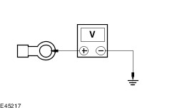
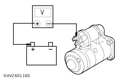
TEST the system for normal operation. | | C2: CHECK FOR VOLTAGE DROP | | | 1 Measure the voltage between the starter motor pin 30, component side and the battery positive terminal with the ignition switch in position III. | | | Is the voltage less than 0.5 volts? Yes No CLEAN and TIGHTEN all positive battery cable connections. TEST the system for normal operation. If the concern persists. INSTALL a new battery to starter motor cable.
REFER to: Battery Cables - 1.6L Duratec-16V (Sigma) (414-01 Battery, Mounting and Cables, Removal and Installation) /
Battery Cables - 1.8L Duratec-HE (MI4)/2.0L Duratec-HE (MI4) (414-01 Battery, Mounting and Cables, Removal and Installation) /
Battery Cables - 1.6L Duratorq-TDCi (DV) Diesel (414-01 Battery, Mounting and Cables, Removal and Installation) /
Battery Cables - 2.0L Duratorq-TDCi (DW) Diesel (414-01 Battery, Mounting and Cables, Removal and Installation).
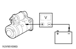
TEST the system for normal operation. | | C3: CHECK FOR GROUND CONNECTION | | | 1 Measure the voltage between the starter motor case and battery negative terminal with the ignition switch in position III. | | | Is the voltage less than 0.5 volts? Yes DIAGNOSE the battery and charging system.
REFER to: Charging System (414-00 Charging System - General Information, Diagnosis and Testing).
No CLEAN and TIGHTEN all battery negative connections, starter motor mounting and body to engine ground straps. TEST the system for normal operation. If the concern persists, INSTALL a new battery negative cable. TEST the system for normal operation. | |