| Diagnosis and Testing Refer to Wiring Diagrams Section 412-00, for schematic and connector information. Special Tool(s) | | Terminal Probe Kit 418-S035 | General Equipment Digital Multimeter (compatible with K-type thermocouple) Worldwide Diagnostic System (WDS) Refrigerant center Thermometer - Fluke 80 PK-8 (FSE number 260 4102 001 07) Inspection and Checking NOTE:The electronic automatic temperature control (EATC) module is integrated into the air conditioning control assembly. - Visually CHECK for any obvious mechanical or electrical damage.
NOTE:Ensure correct locking of the wiring harness connector. Visual Inspection | Mechanical | Electrical | - Refrigerant lines
- Condenser core
- Coolant level
- Drive belt
- A/C compressor
| - Fuses
- Wiring harness
- Connector
| - RECTIFY any obvious causes for a concern found during the visual inspection before performing any further tests. CHECK the operation of the system.
- If the concern is still present after the visual inspection, perform fault diagnosis on the electronic engine management, the charging system, the generic electronic module (GEM) and the instrument cluster (vehicles with EATC: read out the EATC fault memory as well) using WDS and RECTIFY the fault(s) displayed in accordance with the fault description. CHECK the operation of the system.
- For vehicles with no stored fault(s), PROCEED in accordance with the Symptom Chart according to the fault symptom.
- Following checking or elimination of the fault(s) and after completion of operations, the fault memories of all vehicle modules must be READ OUT and any stored faults must be DELETED. READ OUT all fault memories again following a road test.
Refrigerant Circuit - Quick Check WARNING:The air conditioning system is filled with refrigerant R134a. Observe "Health and Safety Precautions". For further information
REFER to: Health and Safety Precautions (100-00 General Information, Description and Operation).
Refrigerant circuit check WARNING:Under certain circumstances, refrigerant lines and A/C components may be extremely hot or cold. Exercising care, touch the refrigerant lines or A/C components in order to check this. Failure to follow these instructions may result in personal injury. When the A/C system is operating, the following conditions should apply: - The refrigerant line from the refrigerant compressor to the condenser must be hot.
- The refrigerant line from the A/C condenser to the fixed orifice tube must be warm, but not so hot as the refrigerant line mentioned above.
- Determine the difference in temperature upstream and downstream of the A/C condenser by measuring the temperatures at the refrigerant lines. The temperature difference should be more than 20° C, depending on the ambient temperature. If the temperature difference is less, check the condenser for contamination or damage to the fins as well as operation of the radiator fans.
- The refrigerant line between the fixed orifice tube and the evaporator must be cold from the point where the fixed orifice tube is installed. Depending on the weather, the refrigerant line may also have ice on its surface.
- The refrigerant line between the evaporator and the A/C compressor including the dehydrator must be cold.
Evaporator outlet line temperature test To test the power of the A/C system, the temperature at the evaporator outlet line must be measured. To do this, the following preconditions must be met: - Open all windows.
- Set the air distribution to the defrost/dashboard position and open all the ventilation nozzles.
- DO NOT switch on recirculated air.
- Select lowest blower switch setting.
- Select lowest temperature setting.
NOTE:The temperature measurement cannot be done with a thermometer which makes no contact. The surface reflection from the metal line may cause incorrect readings. Connect the temperature sensor (Fluke 80 PK-8) to the outlet line of the evaporator. Locate the temperature sensor as close as possible to the evaporator. Connect the temperature sensor to the multimeter. Start the engine and allow it to run at idle speed for several minutes. Switch on the A/C. After three minutes, measure the surface temperature of the evaporator outlet line. If the temperature measured is 4° C or lower, the A/C system is OK. If the temperature is higher, the A/C system may be under-filled. For further information, refer to
REFER to: Air Conditioning (A/C) System Recovery, Evacuation and Charging (412-00 Climate Control System - General Information, General Procedures).
Frequent faults and their causes If the cooling power of the A/C system is not adequate, make certain that the temperature control flap(s) is/are operating correctly. - No or poor cooling performance:
- Blockage or narrowing of a refrigerant line or in the dehydrator. The location of the blockage or narrowing can easily be located by temperature comparisons at the refrigerant lines and the dehydrator. The blockage or restriction is located at the point where the temperature difference is identified. Note: A temperature difference in the area of the fixed orifice tube is normal. If the location of the blockage or narrowing is found, check the corresponding component and renew as applicable. - Sudden drop in cooling performance (after the air conditioning has been switched off for approx. 5 minutes, the cooling performance returns to normal):
- The cause is an iced-up fixed orifice tube because of moisture in the refrigerant circuit. In order to ensure that moisture is completely removed from the refrigerant circuit, the dehydrator should be renewed and the evacuation time should be extended to 2-3 hours. For further information
REFER to: Air Conditioning (A/C) System Recovery, Evacuation and Charging (412-00 Climate Control System - General Information, General Procedures).
Sequence of A/C Request Signal NOTE:The electronic automatic temperature control (EATC) module is integrated into the air conditioning control assembly. NOTE:The generic electronic module (GEM) is an integral part of the central junction box (CJB). After actuating the A/C ON/OFF switch integrated into the A/C control assembly, an A/C request signal is sent from the A/C control assembly (vehicles with EATC: EATC module) to the GEM. From there, the signal is sent to the instrument cluster via the MS-CAN bus. A gateway is installed in the instrument cluster, which establishes the connection between the MS-CAN bus and the HS-CAN bus. After the signal has been converted in the gateway, it is relayed to the powertrain control module (PCM) via the HS-CAN bus. Once all the required parameters have been met, the PCM switches on the refrigerant compressor and thus the A/C system via the A/C clutch relay. Fault Memory Interrogation without WDS - vehicles with electronic automatic temperature control (EATC) NOTE:NOTE: On vehicles equipped with a DVD navigation system with touchscreen, interrogation of the fault memory is only possible using WDS. The climate control system features a self-diagnosis function which can detect and store both current permanent faults as well as intermittent faults which have occurred during normal operation of the vehicle. It is also possible to read out these faults via the display of the EATC module. To read out the fault memory, the ignition key must be turned to the "ON" position and the battery voltage must be between 9 V and 16 V. Activation of self-diagnosis At the controls of the EATC, PRESS the "OFF" and "FOOTWELL" buttons simultaneously for exactly 2 seconds, then PRESS "AUTO" within 1.5 seconds. The self-diagnosis which then starts lasts a few seconds. An animated display appears in the EATC display during this time. Any faults found are displayed on both displays of the EATC in the form of trouble codes. Example: Left-hand display indicates "90", right-hand display indicates "27" - trouble code read out 9027 = Short circuit (short to ground) in circuit of air outlet temperature sensor for the right-hand centre vents. The following table gives information on the possible DTCs and their corresponding meanings. By PRESSING the "DEFROST" button, the fault memory is cleared and diagnosis mode is ended. To end the diagnostic mode without clearing the DTCs, PRESS any other EATC button. Reading out of stored faults At the controls of the EATC, PRESS the "OFF" and "FOOTWELL" buttons simultaneously for exactly 2 seconds, then PRESS "HEAD AREA" within 1.5 seconds. Any stored faults are shown on the EATC display and should be noted for safety reasons. By PRESSING the "DEFROST" button, the fault memory is cleared and diagnosis mode is ended. To end the diagnostic mode without clearing the DTCs, PRESS any other EATC button. Reading out the software version At the controls of the EATC, PRESS the "OFF" and "FOOTWELL" buttons simultaneously for exactly 2 seconds, then PRESS "A/C" within 1.5 seconds. The software version is shown on the EATC display. The output mode can be exited by PRESSING any operating button of the EATC. Fault Code Table - vehicles with electronic automatic temperature control (EATC) Electronic automatic temperature control (EATC) fault code table | Self-test code | Description | Action | | 9027 | Short in circuit for right-hand center vents air outlet temperature sensor (short to ground) | GO to Pinpoint Test N. | | 9028 | Break in circuit for right-hand center vents air outlet temperature sensor | GO to Pinpoint Test N. | | 9029 | Short in circuit for right-hand footwell air outlet temperature sensor (short to ground) | GO to Pinpoint Test O. | | 9030 | Break in circuit for right-hand footwell air outlet temperature sensor | GO to Pinpoint Test O. | | 9200 | Circuit for push buttons, EATC module faulty | CLEAR fault memory. | | If the fault occurs again after a functional test, RENEW the EATC module. | | 9242 | Fault in the circuit of the air recirculation flap actuator | GO to Pinpoint Test G. | | 9251 | Break in circuit for interior temperature sensor | GO to Pinpoint Test Q. | | 9253 | Short in circuit for interior temperature sensor (short to ground) | GO to Pinpoint Test Q. | | 9259 | Break in circuit for left-hand sun load sensor | GO to Pinpoint Test P. | | 9261 | Short in circuit for left-hand sun load sensor (short to ground) | GO to Pinpoint Test P. | | 9262 | Fault in circuit of air flap actuator for defroster/center vents flap | GO to Pinpoint Test K. | | 9263 | Fault in circuit of actuator for air distribution flap | GO to Pinpoint Test J. | | 9342 | Internal control module fault | CLEAR fault memory. | | If the fault occurs again after a functional test, RENEW the EATC module. | | 9676 | Power supply voltage outside tolerance (9 V - 16 V) | GO to Pinpoint Test D. | | A266 | Circuit of left-hand temperature control flap actuator faulty | GO to Pinpoint Test H. | | A267 | Circuit of right-hand temperature control flap actuator faulty | GO to Pinpoint Test I. | | A297 | Break in circuit for left-hand center vents air outlet temperature sensor | GO to Pinpoint Test L. | | A298 | Short in circuit for left-hand center vents air outlet temperature sensor (short to ground) | GO to Pinpoint Test L. | | A299 | Break in circuit for left-hand footwell air outlet temperature sensor | GO to Pinpoint Test M. | | A307 | Short in circuit for left-hand footwell air outlet temperature sensor (short to ground) | GO to Pinpoint Test M. | | A308 | Fault in the circuit of the interior temperature sensor blower | GO to Pinpoint Test R. | | A426 | Break in circuit for right-hand sun load sensor | GO to Pinpoint Test P. | | A427 | Short in circuit for right-hand sun load sensor (short to ground) | GO to Pinpoint Test P. | | A516 | Circuit of the blower control module faulty | GO to Pinpoint Test E. | Symptom Chart Symptom Chart NOTE:The generic electronic module (GEM) is an integral part of the central junction box (CJB). | Symptom | Possible Sources | Action | | Blower motor inoperative/incorrect function - vehicles without electronic automatic temperature control (EATC) | * Fuse(s) * Circuit(s) * Blower motor * Air conditioning control assembly * Blower resistor assembly * Blower relay * Generic electronic module (GEM) | * | | Malfunction of the air recirculation flap | * Fuse(s) * Circuit(s) * Air conditioning control assembly * Electronic automatic temperature control (EATC) module * Actuator – air recirculation flap * Air recirculation flap | * - Vehicles without electronic automatic temperature control (EATC): GO to Pinpoint Test B. * Vehicles with electronic automatic temperature control (EATC): GO to Pinpoint Test G. | | Air conditioning inoperative (blower motor OK) | * Fuse(s) * Circuit(s) * Air conditioning control assembly * Electronic automatic temperature control (EATC) module * Refrigerant high-pressure switch * Refrigerant pressure transducer * Refrigerant low-pressure switch * Air conditioning clutch relay * Air conditioning clutch * Refrigerant quantity * Generic electronic module (GEM) * Powertrain control module (PCM) | * | | Air conditioning control assembly inoperative - vehicles with electronic automatic temperature control (EATC) | * Fuse(s) * Circuit(s) * Electronic automatic temperature control (EATC) module | * | | Blower malfunction - vehicles with electronic automatic temperature control (EATC) (display in the A/C control assembly OK) | * Fuse(s) * Circuit(s) * Electronic automatic temperature control (EATC) module * Blower * Blower control module * Blower relay * Generic electronic module (GEM) * Central junction box (CJB) | * Vehicles built up to 10/2005: GO to Pinpoint Test E. * Vehicles built from 10/2005: GO to Pinpoint Test F. | | Malfunction of left-hand temperature control flap - vehicles with electronic automatic temperature control (EATC) | * Circuit(s) * Left-hand temperature control flap actuator * Left-hand temperature control flap * Electronic automatic temperature control (EATC) module | * | | Malfunction of right-hand temperature control flap - vehicles with electronic automatic temperature control (EATC) | * Circuit(s) * Right-hand temperature control flap actuator * Right-hand temperature control flap * Electronic automatic temperature control (EATC) module | * | | Malfunction of air distribution valve - vehicles with electronic automatic temperature control (EATC) | * Circuit(s) * Air distribution flap actuator * Air distribution flap * Electronic automatic temperature control (EATC) module | * | | Malfunction of air flap actuator - defroster/center vents - vehicles with electronic automatic temperature control (EATC) | * Circuit(s) * Defrost/center vents air flap actuator * Defrost flap * Electronic automatic temperature control (EATC) module | * | | Fault in left-hand centre vents air outlet temperature sensor circuit - vehicles with electronic automatic temperature control (EATC) | * Circuit(s) * Air outlet temperature sensor - centre vents - left side * Electronic automatic temperature control (EATC) module | * | | Fault in left-hand footwell air outlet temperature sensor circuit - vehicles with electronic automatic temperature control (EATC) | * Circuit(s) * Left-hand footwell air outlet temperature sensor * Electronic automatic temperature control (EATC) module | * | | Fault in right-hand centre vents air outlet temperature sensor circuit - vehicles with electronic automatic temperature control (EATC) | * Circuit(s) * Air outlet temperature sensor - centre vents - right side * Electronic automatic temperature control (EATC) module | * | | Fault in right-hand footwell air outlet temperature sensor circuit - vehicles with electronic automatic temperature control (EATC) | * Circuit(s) * Right-hand footwell air outlet temperature sensor * Electronic automatic temperature control (EATC) module | * | | Sun load sensor circuit faulty - vehicles with electronic automatic temperature control (EATC) | * Circuit(s) * Sun load sensor * Electronic automatic temperature control (EATC) module | * | | Passenger compartment temperature sensor circuit faulty - vehicles with electronic automatic temperature control (EATC) | * Circuit(s) * Passenger compartment temperature sensor * Electronic automatic temperature control (EATC) module | * | | Blower interior temperature sensor circuit faulty - vehicles with electronic automatic temperature control (EATC) | * Circuit(s) * Blower interior temperature sensor * Electronic automatic temperature control (EATC) module | * | System Checks | PINPOINT TEST A : BLOWER MOTOR INOPERATIVE/INCORRECT FUNCTION - VEHICLES WITHOUT ELECTRONIC AUTOMATIC TEMPERATURE CONTROL (EATC) | | TEST CONDITIONS | DETAILS/RESULTS/ACTIONS | | A1: CHECK ALL SPEED SETTINGS OF THE BLOWER MOTOR | | | 1 Ignition switch in position II. | | | 2 Switch the blower switch through all switch settings. | | | Is the blower motor inoperative in all the switch positions? Yes No - The blower motor is only inoperative in switch position 4: GO to A15. - The blower motor is inoperative in switch positions 1, 2 and/or 3: GO to A16. | | A2: CHECK FUSE F10 | | | 1 Ignition switch in position 0. | | | 2 CHECK fuse F10 (BJB). | | | Is the fuse OK? Yes No RENEW fuse F10 (30 A). CHECK the operation of the system. If the fuse blows again, LOCATE and REPAIR the short using the Wiring Diagrams. | | A3: CHECK THE EQUIPMENT LEVEL | | | 1 Compare the following systems with the equipment level of the vehicle: - Double locking.
- Footwell lighting.
- Reading lights.
- Anti-theft alarm.
- Headlamp switch-off delay.
| | | Is the vehicle equipped with one of the above systems? Yes No | | A4: CHECK THE VOLTAGE AT FUSE F10 | | | 1 Connect fuse F10 (BJB). | | | 2 Ignition switch in position II. | | | 3 Measure the voltage between fuse F10 (30 A) and ground. | | | Does the meter display battery voltage? Yes No REPAIR the voltage supply to fuse F10 using the Wiring Diagrams. CHECK the operation of the system. | | A5: CHECK VOLTAGE AT BLOWER MOTOR | | | 1 Ignition switch in position 0. | | | 2 Disconnect connector C789 from blower motor. | | | 3 Ignition switch in position II. | | | 4 Measure the voltage between the blower motor, connector C789, pin 1, circuit 15-FA18 (GN/OG), wiring harness side and ground. | | | Does the meter display battery voltage? Yes No LOCATE and REPAIR break in circuit 15-FA18 (GN/OG), between blower motor and fuse F10 using the Wiring Diagrams. CHECK the operation of the system. | | A6: CHECK THE VOLTAGE AT FUSE F10 | | | 1 Connect fuse F10 (BJB). | | | 2 Measure the voltage between fuse F10 (30 A) and ground. | | | Does the meter display battery voltage? Yes No REPAIR the voltage supply to fuse F10 using the Wiring Diagrams. CHECK the operation of the system. | | A7: CHECK THE VOLTAGE AT THE BLOWER MOTOR | | | 1 Disconnect connector C789 from blower motor. | | | 2 Ignition switch in position II. | | | 3 Measure the voltage between the blower motor, connector C789, pin 1, circuit 15-FA18 (GN/OG), wiring harness side and ground. | | | Is battery voltage measured? Yes No | | A8: CHECK VOLTAGE AT THE BLOWER RELAY | | | 1 Ignition switch in position 0. | | | 2 Disconnect blower relay from socket C1010 (BJB). | | | 3 Measure the voltage between the blower relay, socket C1010, pin 1, circuit 30-FA23 (RD), wiring harness side and ground. | | | 4 Measure the voltage between the blower relay, socket C1010, pin 3, circuit 30-FA24 (RD), wiring harness side and ground. | | | Is battery voltage registered following both measurements? Yes No - If battery voltage is not measured during one of the measurements:LOCATE and REPAIR the break in the relevant circuit between the blower relay and soldered connection S119 using the Wiring Diagrams. CHECK the operation of the system. - Battery voltage not measured in any case:LOCATE and REPAIR the break in circuit 30-FA23A (RD) between soldered connection S119 and fuse F10 using the Wiring Diagrams. CHECK the operation of the system. | | A9: CHECK CIRCUIT BETWEEN THE BLOWER RELAY AND THE BLOWER MOTOR FOR OPEN CIRCUIT | | | 1 Measure the resistance between the blower relay, socket C1010, pin 5, circuit 15-FA18 (GN/OG), wiring harness side and blower motor, connector C789, pin 1, circuit 15-FA18 (GN/OG), wiring harness side. | | | Is a resistance of less than 2 Ohms registered? Yes No LOCATE and REPAIR the break in the circuit between the blower relay and the blower motor using the Wiring Diagrams. CHECK the operation of the system. | | A10: CHECK BLOWER RELAY | | | 1 Check blower relay according to the component test at the end of this section. | | | Is the blower relay OK? Yes No RENEW the blower relay. CHECK the operation of the system. | | A11: CHECK CIRCUIT BETWEEN THE BLOWER RELAY AND THE CJB FOR OPEN CIRCUIT | NOTE:If the generic electronic module (GEM) is changed, the new one must be configured. For this purpose, the vehicle-specific data is read out of the module to be replaced using WDS and is transferred to the new module
REFER to: Module Configuration (418-01 Module Configuration, General Procedures).
. | | | 1 Disconnect connector C95 from CJB. | | | 2 Measure the resistance between the blower relay, socket C1010, pin 2, circuit 31S-FA23 (BK/BU), wiring harness side and CJB, connector C95, pin 32, circuit 31S-FA23 (BK/BU), wiring harness side. | | | Is a resistance of less than 2 Ohms registered? Yes CHECK the CJB and RENEW as necessary. CHECK the operation of the system. No LOCATE and REPAIR the break in circuit 31S-FA23 (BK/BU) between the blower relay and CJB using the Wiring Diagrams. CHECK the operation of the system. | | A12: CHECK GROUND CONNECTION OF BLOWER MOTOR | | | 1 Ignition switch in position 0. | | | 2 Set the blower switch to position 4. | | | 3 Measure the resistance between the blower motor, connector C789, pin 2, circuit 31S-FA18 (BK/RD), wiring harness side and ground. | | | Is a resistance of less than 2 Ohms registered? Yes RENEW the blower motor. CHECK the operation of the system. No | | A13: CHECK THE CIRCUIT BETWEEN THE BLOWER MOTOR AND THE BLOWER SWITCH FOR OPEN CIRCUIT | | | 1 Disconnect connector C380 from blower switch. | | | 2 Measure the resistance between the blower motor, connector C789, pin 2, circuit 31S-FA18 (BK/RD), wiring harness side and the blower switch, connector C380, pin 4, circuit 31S-FA33 (BK/OG), wiring harness side. | | | Is a resistance of less than 2 Ohms registered? Yes No LOCATE and REPAIR the break in circuit 31S-FA18 (BK/RD) between the blower motor and soldered connection S24 using the Wiring Diagrams. CHECK the operation of the system. | | A14: CHECK THE GROUND CONNECTION OF THE BLOWER SWITCH | | | 1 Measure the resistance between the blower switch, connector C380, pin 5, circuit 31-FA25 (BK), wiring harness side and ground. | | | Is a resistance of less than 2 Ohms registered? Yes RENEW the blower switch. CHECK the operation of the system. No LOCATE and REPAIR the break in the circuit between the blower switch and ground connection G20 using the Wiring Diagrams. CHECK the operation of the system. | | A15: CHECK FOR OPEN CIRCUIT BETWEEN THE BLOWER MOTOR AND BLOWER SWITCH (4TH SPEED INOPERATIVE) | | | 1 Ignition switch in position 0. | | | 2 Disconnect connector C789 from blower motor. | | | 3 Disconnect connector C380 from blower switch. | | | 4 Measure the resistance between the blower motor, connector C789, pin 2, circuit 31S-FA18 (BK/RD), wiring harness side and the blower switch, connector C380, pin 4, circuit 31S-FA33 (BK/OG), wiring harness side. | | | Is a resistance of less than 2 Ohms registered? Yes RENEW the blower switch. CHECK the operation of the system. No LOCATE and REPAIR the break in circuit 31S-FA33 (BK/OG) between the blower switch and soldered connection S24 using the Wiring Diagrams. CHECK the operation of the system. | | A16: CHECK THE BLOWER SWITCH | | | 1 Ignition switch in position 0. | | | 2 Disconnect connector C380 from blower switch. | | | 3 Ignition switch in position II. | | | 4 Measure the voltage between the blower switch, connector C380, pin 3, circuit 31S-FA32 (BK/BU), wiring harness side and ground. | | | 5 Measure the voltage between the blower switch, connector C380, pin 2, circuit 31S-FA31 (BK/YE), wiring harness side and ground. | | | 6 Measure the voltage between the blower switch, connector C380, pin 1, circuit 31S-FA30 (BK/WH), wiring harness side and ground. | | | Is battery voltage measured in all cases? Yes RENEW the blower switch. CHECK the operation of the system. No - Battery voltage not measured in any case: GO to A17. - Battery voltage not measured in one/two cases: GO to A18. | | A17: CHECK VOLTAGE AT BLOWER RESISTOR ASSEMBLY | | | 1 Ignition switch in position 0. | | | 2 Disconnect connector C470 from blower resistor assembly. | | | 3 Ignition switch in position II. | | | 4 Measure the voltage between the blower resistor assembly, connector C470, pin 4, circuit 31S-FA33A (BK/OG), wiring harness side and ground. | | | Does the meter display battery voltage? Yes RENEW the blower resistor assembly. CHECK the operation of the system. No LOCATE and REPAIR the break in circuit 31S-FA33A (BK/OG) between the blower resistor assembly and soldered connection S24 using the Wiring Diagrams. CHECK the operation of the system. | | A18: CHECK THE CIRCUIT BETWEEN THE BLOWER RESISTOR ASSEMBLY AND THE BLOWER SWITCH FOR OPEN CIRCUIT | | | 1 Ignition switch in position 0. | | | 2 Disconnect connector C470 from blower resistor assembly. | | | 3 Measure the resistance between the blower resistor, connector C470, pin 3, circuit 31S-FA32 (BK/BU), wiring harness side and the blower switch, connector C380, pin 3, circuit 31S-FA32 (BK/BU), wiring harness side. | | | 4 Measure the resistance between the blower resistor assembly, connector C470, pin 1, circuit 31S-FA31 (BK/YE), wiring harness side and the blower switch, connector C380, pin 2, circuit 31S-FA31 (BK/YE), wiring harness side. | | | 5 Measure the resistance between the blower resistor, connector C470, pin 2, circuit 31S-FA30 (BK/WH), wiring harness side and the blower switch, connector C380, pin 1, circuit 31S-FA30 (BK/WH), wiring harness side. | | | Is a resistance of less than 2 Ohms measured in all of the cases? Yes RENEW the blower resistor assembly. CHECK the operation of the system. No LOCATE and REPAIR the break in the relevant circuit between the blower resistor assembly and the blower switch using the Wiring Diagrams. CHECK the operation of the system. | | PINPOINT TEST B : MALFUNCTION OF THE RECIRCULATED AIR FLAP - VEHICLES WITHOUT ELECTRONIC AUTOMATIC TEMPERATURE CONTROL (EATC) | NOTE:The air recirculation flap is actuated by means of a DC motor. This is activated for a maximum of 7 seconds by the A/C control assembly following actuation of the recirculated air button. Opening and closing of the air recirculation flap is performed by reversing the polarity of the applied voltage. | NOTE:Recirculated air mode is not available if the air distribution control is set to "Defrost/demist windscreen". | | TEST CONDITIONS | DETAILS/RESULTS/ACTIONS | | B1: CHECK THE EQUIPMENT LEVEL | | | 1 Compare the following systems with the equipment level of the vehicle: - Double locking.
- Footwell lighting.
- Reading lights.
- Anti-theft alarm.
- Headlamp switch-off delay.
| | | Is the vehicle equipped with one of the above systems? Yes No | | B2: CHECK FUSE F43 | | | 1 Ignition switch in position 0. | | | 2 CHECK fuse F43 (CJB). | | | Is the fuse OK? Yes No RENEW fuse F43 (10 A). CHECK the operation of the system. If the fuse blows again, LOCATE and REPAIR the short using the Wiring Diagrams. | | B3: CHECK THE VOLTAGE AT FUSE F43 | | | 1 Connect fuse F43 (CJB). | | | 2 Measure the voltage between fuse F43 (10 A) and ground. | | | Does the meter display battery voltage? Yes No REPAIR the voltage supply to fuse F43 using the Wiring Diagrams. CHECK the operation of the system. | | B4: CHECK FUSE F70 | | | 1 Ignition switch in position 0. | | | 2 CHECK fuse F70 (CJB). | | | Is the fuse OK? Yes No RENEW fuse F70 (10 A). CHECK the operation of the system. If the fuse blows again, LOCATE and REPAIR the short using the Wiring Diagrams. | | B5: CHECK THE VOLTAGE AT FUSE F70 | | | 1 Connect fuse F70 (CJB). | | | 2 Ignition switch in position II. | | | 3 Measure the voltage between fuse F70 (10 A) and ground. | | | Does the meter display battery voltage? Yes No REPAIR the voltage supply to fuse F70 using the Wiring Diagrams. CHECK the operation of the system. | | B6: CHECK VOLTAGE AT THE AIR RECIRCULATION FLAP ACTUATOR | | | 1 Ignition switch in position 0. | | | 2 Disconnect Connector C538 from air recirculation flap actuator. | | | 3 Ignition switch in position II. | | | 4 Set the air distribution control switch to footwell. | | | 5 Measure the voltage at the air recirculation flap actuator, connector C538, between pin 2 and pin 4, wiring harness side. | | | 6 Actuate the air recirculation switch several times during the measurement. | | | Is a voltage of at least 10 V measured with alternating polarity? Yes CHECK the recirculated air flap for ease of movement and correct operation. If the air recirculation flap is OK, RENEW the air recirculation flap actuator. CHECK the operation of the system. No | | B7: CHECK THE EQUIPMENT LEVEL | | | 1 Compare the following systems with the equipment level of the vehicle: - Double locking.
- Footwell lighting.
- Reading lights.
- Anti-theft alarm.
- Headlamp switch-off delay.
| | | Is the vehicle equipped with one of the above systems? Yes No | | B8: CHECK THE VOLTAGE AT THE AIR CONDITIONING CONTROL ASSEMBLY | | | 1 Ignition switch in position 0. | | | 2 Disconnect Connector C378 from A/C control assembly. | | | 3 Measure the voltage between the A/C control assembly, connector C378, pin 1, circuit 29-FA13 (OG), wiring harness side and ground. | | | Is battery voltage measured? Yes No | | B9: CHECK FOR OPEN CIRCUIT BETWEEN THE AIR CONDITIONING CONTROL ASSEMBLY AND THE CJB | | | 1 Disconnect Connector C102 from CJB. | | | 2 Measure the resistance between the A/C control assembly, connector C378, pin 1, circuit 29-FA13 (OG), wiring harness side and the CJB, connector C102, pin 10, circuit 29-FA13 (OG), wiring harness side. | | | Is a resistance of less than 2 Ohms registered? Yes CHECK the CJB and RENEW as necessary. CHECK the operation of the system. No LOCATE and REPAIR the break in the circuit between the CJB and the A/C control assembly using the Wiring Diagrams. CHECK the operation of the system. | | B10: CHECK THE VOLTAGE AT THE AIR CONDITIONING CONTROL ASSEMBLY | | | 1 Ignition switch in position 0. | | | 2 Disconnect Connector C378 from A/C control assembly. | | | 3 Ignition switch in position II. | | | 4 Measure the voltage between the A/C control assembly, connector C378, pin 8, circuit 15-FA13 (GN/RD), wiring harness side and ground. | | | Does the meter display battery voltage? Yes No | | B11: CHECK FOR OPEN CIRCUIT BETWEEN THE AIR CONDITIONING CONTROL ASSEMBLY AND THE CJB | | | 1 Disconnect Connector C102 from CJB. | | | 2 Measure the resistance between the A/C control assembly, connector C378, pin 8, circuit 15-FA13 (GN/RD), wiring harness side and the CJB, connector C102, pin 5, circuit 15-FA13 (GN/RD), wiring harness side. | | | Is a resistance of less than 2 Ohms registered? Yes CHECK the CJB and RENEW as necessary. CHECK the operation of the system. No LOCATE and REPAIR the break in the circuit between the CJB and the A/C control assembly using the Wiring Diagrams. CHECK the operation of the system. | | B12: CHECK THE GROUND CONNECTION OF THE AIR CONDITIONING CONTROL ASSEMBLY | | | 1 Ignition switch in position 0. | | | 2 Measure the resistance between the A/C control assembly, connector C378, pin 4, circuit 91-FA13 (BK/OG), wiring harness side and ground. | | | Is a resistance of less than 2 Ohms registered? Yes No LOCATE and REPAIR break in circuit 91-FA13 (BK/OG) between the A/C control assembly and soldered connection S10 (vehicles built from 10/2003: soldered connection S12) using the Wiring Diagrams. CHECK the operation of the system. | | B13: CHECK FOR OPEN CIRCUIT BETWEEN THE AIR RECIRCULATION FLAP ACTUATOR AND THE A/C CONTROL ASSEMBLY | | | 1 Measure the resistance between the air recirculation flap actuator, connector C538, pin 2, circuit 32-FA76 (WH/BU) (RHD vehicles: pin 4, circuit 32-FA76A (WH/BU)), wiring harness side and the A/C control assembly, connector C378, pin 7, circuit 32-FA76 (WH/BU) (RHD vehicles: circuit 32-FA76A (WH/BU)), wiring harness side. | | | 2 Measure the resistance between the air recirculation flap actuator, connector C538, pin 4, circuit 33-FA76 (YE/BU) (RHD vehicles: pin 2, circuit 33-FA76A (YE/BU)), wiring harness side and the A/C control assembly, connector C378, pin 6, circuit 33-FA76 (YE/BU) (RHD vehicles: circuit 33-FA76A (YE/BU)), wiring harness side. | | | Is a resistance of less than 2 Ohms measured in both cases? Yes CHECK and if necessary RENEW the A/C control assembly. CHECK the operation of the system. No LOCATE and REPAIR the break in the respective circuit between the A/C control assembly and the air recirculation flap actuator using the Wiring Diagrams. CHECK the operation of the system. | | PINPOINT TEST C : AIR CONDITIONING INOPERATIVE (BLOWER MOTOR OK) | | TEST CONDITIONS | DETAILS/RESULTS/ACTIONS | | C1: CHECK FUSE F27 | | | 1 Ignition switch in position 0. | | | 2 CHECK fuse F27 (BJB). | | | Is the fuse OK? Yes No RENEW fuse F27 (10 A). CHECK the operation of the system. If the fuse blows again, LOCATE and REPAIR the short using the Wiring Diagrams. | | C2: CHECK THE VOLTAGE AT FUSE F27 | | | 1 Connect fuse F27 (BJB). | | | 2 Measure the voltage between fuse F27 (10 A) and ground. | | | Does the meter display battery voltage? Yes No REPAIR the voltage supply to fuse F27 using the Wiring Diagrams. CHECK the operation of the system. | | C3: CHECK FUSE F35 | | | 1 CHECK fuse F35 (BJB). | | | Is the fuse OK? Yes No RENEW fuse F35 (10 A). CHECK the operation of the system. If the fuse blows again, LOCATE and REPAIR the short using the Wiring Diagrams. | | C4: CHECK THE VOLTAGE AT FUSE F35 | | | 1 Connect fuse F35 (BJB). | | | 2 Ignition switch in position II. | | | 3 Measure the voltage between fuse F35 (10 A) and ground. | | | Does the meter display battery voltage? Yes No REPAIR the voltage supply to fuse F35 using the Wiring Diagrams. CHECK the operation of the system. | | C5: CHECK THE VOLTAGE AT THE AIR CONDITIONING CLUTCH RELAY | | | 1 Ignition switch in position 0. | | | 2 Disconnect A/C clutch relay C1011 (BJB). | | | 3 Measure the voltage between the A/C clutch relay, socket C1011, pin 3, circuit 30-FA2 (RD), wiring harness side and ground. | | | Does the meter display battery voltage? Yes No LOCATE and RECTIFY the break in circuit 30-FA2 (RD) between fuse F27 and the the A/C clutch relay using the Wiring Diagrams. CHECK the operation of the system. | | C6: CHECK THE CONTROL VOLTAGE AT THE AIR CONDITIONING CLUTCH RELAY | | | 1 Ignition switch in position II. | | | 2 Measure the voltage between the A/C clutch relay, socket C1011, pin 1, circuit 15-FA11 (GN/YE) (vehicles with a diesel engine: circuit 15-FA11A (GN/YE)), wiring harness side and ground. | | | Is battery voltage measured? Yes No LOCATE and REPAIR the break in circuit 15-FA11 (GN/YE), between fuse F35 and the A/C clutch relay using the Wiring Diagrams. CHECK the operation of the system. | | C7: CHECK THE CIRCUIT OF THE A/C CLUTCH | | | 1 Ignition switch in position 0. | | | 2 Use a fused test cable (10 A) to bridge the air conditioning clutch relay, socket C1011, pin 3 and pin 5, wiring harness side. | | | 3 Check the operation of the air conditioning clutch. | | | Does the air conditioning clutch work? Yes No | | C8: CHECK FOR OPEN CIRCUIT BETWEEN AIR CONDITIONING CLUTCH RELAY AND AIR CONDITIONING CLUTCH | | | 1 Disconnect Connector C952 (vehicles with diesel engine: C957) from A/C clutch. | | | 2 Measure the resistance between the A/C clutch relay, socket C1011, pin 5, circuit 15S-FA6 (GN/YE), wiring harness side and the A/C clutch, connector C952, pin 1 (vehicles with diesel engine: connector C957, pin 2), circuit 15S-FA6 (GN/YE) (vehicles with 1.6L Duratorq-TDCi (DV) diesel engine (81 kW) with diesel particulate filter: circuit 15S-FA6B (GN/YE), vehicles with diesel engine, except vehicles with the 1.6L Duratorq-TDCi (DV) diesel engine (81 kW) with diesel particulate filter and vehicles with 2.0L Duratorq-TDCi (DW) diesel engine: circuit 15S-FA6C (GN/YE), wiring harness side. | | | Is a resistance of less than 2 Ohms registered? Yes No LOCATE and REPAIR the open circuit between the air conditioning clutch relay and the air conditioning clutch using the Wiring Diagrams. CHECK the operation of the system. | | C9: CHECK THE GROUND CONNECTION OF THE A/C CLUTCH | | | 1 Measure the resistance between the A/C clutch, connector C952, pine 2 (vehicles with a diesel engine: connector C957, pin 1), circuit 31-FA6 (BK) (vehicles with 1.6L Duratorq-TDCi (DV) diesel engine (81 kW) with diesel particulate filter: circuit 31-FA6B (BK), vehicles with diesel engine, except vehicles with the 1.6L Duratorq-TDCi (DV) diesel engine (81 kW) with diesel particulate filter and vehicles with 2.0L Duratorq-TDCi (DW) diesel engine: circuit 31-FA6C (BK)), wiring harness side and ground. | | | Is a resistance of less than 2 Ohms registered? Yes RENEW the air conditioning clutch. CHECK the operation of the system. No LOCATE and REPAIR open circuit between the A/C clutch and ground connection G68 (vehicles with diesel engine: ground connection G57) using the Wiring Diagrams. CHECK the operation of the system. | | C10: CHECK THE A/C REQUEST SIGNAL IN THE POWERTRAIN CONTROL MODULE (PCM) | | | 1 Connect the diagnostic tool. | | | 2 Switch on the blower. | | | 3 Switch on the air-conditioning system. | | | 4 Using the diagnostic tester, select the PCM and check in the data logger whether an A/C request signal is displayed. | | | Is an A/C request signal displayed in the data logger of the PCM? Yes No - Vehicles without electronic automatic temperature control (EATC): GO to C11. - Vehicles with electronic automatic temperature control (EATC): CHECK the EATC module, if necessary INSTALL a new one. CHECK the operation of the system. | | C11: CHECK THE A/C REQUEST SIGNAL IN THE GENERIC ELECTRONIC MODULE (GEM) | NOTE:If the generic electronic module (GEM) is changed, the new one must be configured. For this purpose, the vehicle-specific data is read out of the module to be replaced using WDS and is transferred to the new module.
REFER to: Module Configuration (418-01 Module Configuration, General Procedures).
| NOTE:The generic electronic module (GEM) is an integral part of the central junction box (CJB). | | | 1 Switch on the blower. | | | 2 Switch on the air-conditioning system. | | | 3 Using the diagnostic tester, select the GEM and check in the data logger whether an A/C request signal is displayed. | | | Is an A/C request signal displayed in the data logger of the GEM? Yes TEST the GEM and RENEW as necessary. CHECK the operation of the system. No | | C12: CHECK SIGNAL FROM A/C ON/OFF SWITCH AT CJB | | | 1 Ignition switch in position 0. | | | 2 Disconnect connector C103 from CJB. | | | 3 Ignition switch in position II. | | | 4 Set the blower switch to position 1. | | | 5 Switch on the air-conditioning system. | | | 6 Measure the voltage between the CJB, connector C103, pin 13, circuit 8-FA9 (WH/GN), wiring harness side and ground. | | | Does the meter display battery voltage? Yes No | | C13: CHECK FOR OPEN CIRCUIT BETWEEN THE A/C CONTROL ASSEMBLY AND THE CJB | | | 1 Ignition switch in position 0. | | | 2 Disconnect Connector C378 from A/C control assembly. | | | 3 Measure the resistance between the A/C control assembly, connector C378, pin 2, circuit 8-FA9 (WH/GN), wiring harness side and the CJB, connector C103, pin 13, circuit 8-FA9 (WH/GN) wiring harness side. | | | Is a resistance of less than 2 Ohms registered? Yes No LOCATE and REPAIR the break in circuit 8-FA9 (WH/GN) between the A/C control assembly and the CJB using the Wiring Diagrams. CHECK the operation of the system. | | C14: CHECK CIRCUIT BETWEEN THE A/C CONTROL ASSEMBLY AND THE CJB FOR A SHORT TO GROUND | | | 1 Measure the resistance between the A/C control assembly, connector C378, pin 2, circuit 8-FA9 (WH/GN), wiring harness side and ground. | | | Is a resistance of more than 10,000 Ohms measured? Yes CHECK and if necessary RENEW the A/C control assembly. CHECK the operation of the system. No LOCATE and REPAIR the short to ground in circuit 8-FA9 (WH/GN) between the A/C control assembly and the CJB using the Wiring Diagrams. CHECK the operation of the system. | | C15: CHECK VOLTAGE AT REFRIGERANT LOW-PRESSURE SWITCH | | | 1 Ignition switch in position 0. | | | 2 Disconnect connector C692 from refrigerant low-pressure switch. | | | 3 Start the engine and run it at idle speed. | | | 4 Measure the voltage between the refrigerant low-pressure switch, connector C692, pin 4, circuit 91S-RE8 (BK/YE), wiring harness side and ground. | | | Does the meter display battery voltage? Yes No - Vehicles with 1.6L Duratorq-TDCI (DV) diesel engine: GO to C16. - Vehicles with 1.8L Duratorq-TDCi (Lynx) diesel engine/2.0L Duratorq-TDCi (DW) diesel engine: GO to C17. - Vehicles with 1.8L Duratec-HE (MI4)/2.0L Duratec-HE (MI4) engine: GO to C18. - Vehicles with 1.6L Duratec-16V (Sigma) engine/1.6L Duratec-16V Ti-VCT (Sigma) engine: GO to C19. | | C16: CHECK FOR OPEN CIRCUIT BETWEEN THE REFRIGERANT LOW-PRESSURE SWITCH AND THE PCM - VEHICLES WITH 1.6L DURATORQ-TDCI (DV) DIESEL ENGINE | NOTE:If the powertrain control module (PCM) is changed, the new one must be programmed. For this purpose, the vehicle-specific data is read out of the module to be replaced using WDS and is transferred to the new module.
REFER to: Module Configuration (418-01 Module Configuration, General Procedures).
| | | 1 Ignition switch in position 0. | | | 2 Disconnect connector C418 from PCM. | | | 3 Measure the resistance between the refrigerant low-pressure switch, connector C692, pin 4, circuit 91S-RE8 (BK/YE), wiring harness side and PCM, connector C418, pin C4, circuit 91S-RE8 (BK/YE), wiring harness side. | | | Is a resistance of less than 2 Ohms registered? Yes CHECK the PCM and RENEW if necessary. CHECK the operation of the system. No LOCATE and REPAIR the break in circuit 91S-RE8 (BK/YE) between the refrigerant low-pressure switch and the PCM using the Wiring Diagrams. CHECK the operation of the system. | | C17: CHECK FOR OPEN CIRCUIT BETWEEN THE REFRIGERANT LOW-PRESSURE SWITCH AND THE PCM - VEHICLES WITH 1.8L DURATORQ-TDCI (LYNX) DIESEL ENGINE/2.0L DURATORQ-TDCI (DW) DIESEL ENGINE | NOTE:If the powertrain control module (PCM) is changed, the new one must be programmed. For this purpose, the vehicle-specific data is read out of the module to be replaced using WDS and is transferred to the new module.
REFER to: Module Configuration (418-01 Module Configuration, General Procedures).
| | | 1 Ignition switch in position 0. | | | 2 Disconnect connector C418 from PCM. | | | 3 Measure the resistance between the refrigerant low-pressure switch, connector C692, pin 4, circuit 91S-RE8 (BK/YE), wiring harness side and the PCM, connector C418, pin H2, circuit 91S-RE8 (BK/YE) (vehicles built from 10/2003: circuit 91S-RE8A (BK/YE)), wiring harness side. | | | Is a resistance of less than 2 Ohms registered? Yes CHECK the PCM and RENEW if necessary. CHECK the operation of the system. No LOCATE and REPAIR the open circuit between the refrigerant low-pressure switch and the PCM using the Wiring Diagrams. CHECK the operation of the system. | | C18: CHECK FOR OPEN CIRCUIT BETWEEN THE REFRIGERANT LOW-PRESSURE SWITCH AND THE PCM - VEHICLES WITH 1.8L DURATEC-HE (MI4)/2.0L DURATEC-HE (MI4) ENGINE | NOTE:If the powertrain control module (PCM) is changed, the new one must be programmed. For this purpose, the vehicle-specific data is read out of the module to be replaced using WDS and is transferred to the new module.
REFER to: Module Configuration (418-01 Module Configuration, General Procedures).
| | | 1 Ignition switch in position 0. | | | 2 Disconnect connector C690 from PCM. | | | 3 Measure the resistance between the refrigerant low-pressure switch, connector C692, pin 4, circuit 91S-RE8 (BK/YE), wiring harness side and PCM, connector C690, pin 14, circuit 91S-RE8 (BK/YE), wiring harness side. | | | Is a resistance of less than 2 Ohms registered? Yes CHECK the PCM and RENEW if necessary. CHECK the operation of the system. No LOCATE and REPAIR the break in circuit 91S-RE8 (BK/YE) between the refrigerant low-pressure switch and the PCM using the Wiring Diagrams. CHECK the operation of the system. | | C19: CHECK FOR OPEN CIRCUIT BETWEEN THE REFRIGERANT LOW PRESSURE SWITCH AND THE PCM - VEHICLES WITH 1.6L DURATEC-16V (SIGMA) ENGINE/1.6L DURATEC-16V TI-VCT (SIGMA) ENGINE | NOTE:If the powertrain control module (PCM) is changed, the new one must be programmed. For this purpose, the vehicle-specific data is read out of the module to be replaced using WDS and is transferred to the new module.
REFER to: Module Configuration (418-01 Module Configuration, General Procedures).
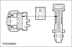
| | | 1 Ignition switch in position 0. | | | 2 Disconnect connector C594 from PCM. | | | 3 Measure the resistance between the refrigerant low-pressure switch, connector C692, pin 4, circuit 91S-RE8 (BK/YE), wiring harness side and PCM, connector C594, pin F22, circuit 91S-RE8 (BK/YE), wiring harness side. | | | Is a resistance of less than 2 Ohms registered? Yes CHECK the PCM and RENEW if necessary. CHECK the operation of the system. No LOCATE and REPAIR the break in circuit 91S-RE8 (BK/YE) between the refrigerant low-pressure switch and the PCM using the Wiring Diagrams. CHECK the operation of the system. | | C20: CHECK GROUND CONNECTION OF REFRIGERANT LOW-PRESSURE SWITCH | | | 1 Ignition switch in position 0. | | | 2 Measure the resistance between the refrigerant low-pressure switch, connector C692, pin 1, circuit 91-FA17A (BK/RD) (vehicles with diesel engine: circuit 91S-FA17 (BK/RD)), wiring harness side and ground. | | | Is a resistance of less than 2 Ohms registered? Yes No - All except vehicles with diesel engines:LOCATE and REPAIR the open circuit between the refrigerant low-pressure switch and ground connection G31 using the Wiring Diagrams. CHECK the operation of the system. | | C21: CHECK REFRIGERANT LOW-PRESSURE SWITCH | | | 1 Measure the resistance at the refrigerant low-pressure switch, connector C692, between pin 1 and pin 4, component side. | | | Is a resistance of less than 2 Ohms registered? Yes No CHECK refrigerant quantity.
REFER to: Air Conditioning (A/C) System Recovery, Evacuation and Charging (412-00 Climate Control System - General Information, General Procedures).
If the refrigerant quantity is in accordance with manufacturer's specifications, RENEW the refrigerant low-pressure switch. CHECK the operation of the system. | | C22: CHECK AIR CONDITIONING CLUTCH RELAY | | | 1 Check the A/C clutch relay according to the component check at the end of the section. | | | Is the air conditioning clutch relay OK? Yes - Vehicles with 1.6L Duratorq-TDCI (DV) diesel engine: GO to C23. - Vehicles with 1.8L Duratorq-TDCi (Lynx) diesel engine/2.0L Duratorq-TDCi (DW) diesel engine: GO to C24. - All except vehicles with diesel engines: GO to C25. No RENEW the air conditioning clutch relay. CHECK the operation of the system. | | C23: CHECK FOR OPEN CIRCUIT BETWEEN THE A/C CLUTCH RELAY AND THE PCM - VEHICLES WITH 1.6L DURATORQ-TDCI (DV) DIESEL ENGINE | NOTE:If the powertrain control module (PCM) is changed, the new one must be programmed. For this purpose, the vehicle-specific data is read out of the module to be replaced using WDS and is transferred to the new module.
REFER to: Module Configuration (418-01 Module Configuration, General Procedures).
| | | 1 Disconnect connector C419 from PCM. | | | 2 Measure the resistance between the PCM, connector C419, pin E2, circuit 31S-FA11 (BK/YE), wiring harness side and the A/C clutch relay, socket C1011, pin 2, circuit 31S-FA11 (BK/YE), wiring harness side. | | | Is a resistance of less than 2 Ohms registered? Yes CHECK the PCM and RENEW if necessary. CHECK the operation of the system. No LOCATE and RECTIFY the break in circuit 31S-FA11 (BK/YE) between PCM and the air conditioning clutch relay using the Wiring Diagrams. CHECK the operation of the system. | | C24: CHECK FOR OPEN CIRCUIT BETWEEN THE A/C CLUTCH RELAY AND THE PCM - VEHICLES WITH 1.8L DURATORQ-TDCI (LYNX) DIESEL ENGINE/2.0L DURATORQ-TDCI (DW) DIESEL ENGINE | NOTE:If the powertrain control module (PCM) is changed, the new one must be programmed. For this purpose, the vehicle-specific data is read out of the module to be replaced using WDS and is transferred to the new module.
REFER to: Module Configuration (418-01 Module Configuration, General Procedures).
| | | 1 Disconnect connector C418 from PCM. | | | 2 Measure the resistance between the PCM, connector C418, pin D4, circuit 31S-FA11 (BK/YE) (vehicles built from 10/2003: circuit 31S-FA11A (BK/YE)), wiring harness side and the A/C clutch relay, socket C1011, pin 2, circuit 31S-FA11 (BK/YE), wiring harness side. | | | Is a resistance of less than 2 Ohms registered? Yes CHECK the PCM and RENEW if necessary. CHECK the operation of the system. No LOCATE and REPAIR the open circuit between the PCM and the A/C clutch relay using the Wiring Diagrams. CHECK the operation of the system. | | C25: CHECK THE VOLTAGE AT THE REFRIGERANT PRESSURE TRANSDUCER | | | 1 Disconnect Connector C965 from refrigerant pressure transducer. | | | 2 Ignition switch in position II. | | | 3 Measure the voltage between the refrigerant pressure transducer, connector C965, pin 2, circuit 7-FA88 (YE/VT) (vehicles with 1.8L Duratec-HE (M14) engine/2.0L Duratec-HE (MI4) engine built from 10/2003: circuit 7-FA88A (YE/VT)), wiring harness side and ground. | | | Is a voltage of approx. 5 volts measured? Yes No - Vehicles with 1.6L Duratec-16V (Sigma) engine/1.6L Duratec-16V Ti-VCT (Sigma) engine: GO to C32. - Vehicles with 1.8L Duratec-HE (MI4)/2.0L Duratec-HE (MI4) engine: GO to C33. | | C26: CHECK THE CONTROL VOLTAGE AT THE REFRIGERANT PRESSURE TRANSDUCER | | | 1 Measure the voltage between the refrigerant pressure transducer, connector C965, pin 3, circuit 8-FA88 (WH/VT) (vehicles with 1.8L Duratec-HE (M14) engine/2.0L Duratec-HE (MI4) engine built from 10/2003: circuit 8-FA88A (WH/VT)), wiring harness side and ground. | | | Is a voltage of approx. 4 volts measured? Yes No - Vehicles with 1.6L Duratec-16V (Sigma) engine/1.6L Duratec-16V Ti-VCT (Sigma) engine: GO to C28. - Vehicles with 1.8L Duratec-HE (MI4)/2.0L Duratec-HE (MI4) engine: GO to C30. | | C27: CHECK THE GROUND CONNECTION OF THE REFRIGERANT PRESSURE TRANSDUCER | | | 1 Ignition switch in position 0. | | | 2 Measure the resistance between the refrigerant pressure transducer, connector C965, pin 1, circuit 9-FA88 (BN/WH) (vehicles with 1.8L Duratec-HE (M14) engine/2.0L Duratec-HE (MI4) engine built from 10/2003: circuit 9-FA88A (BN/WH)), wiring harness side and ground. | | | Is a resistance of less than 2 Ohms registered? Yes - Vehicles with 1.6L Duratec-16V (Sigma) engine/1.6L Duratec-16V Ti-VCT (Sigma) engine: GO to C29. - Vehicles with 1.8L Duratec-HE (MI4)/2.0L Duratec-HE (MI4) engine: GO to C31. No - Vehicles with 1.6L Duratec-16V (Sigma) engine/1.6L Duratec-16V Ti-VCT (Sigma) engine: GO to C34. - Vehicles with 1.8L Duratec-HE (MI4)/2.0L Duratec-HE (MI4) engine: GO to C35. | | C28: CHECK FOR OPEN CIRCUIT BETWEEN THE REFRIGERANT PRESSURE SWITCH AND THE PCM - VEHICLES WITH 1.6L DURATEC-16V (SIGMA) ENGINE/1.6L DURATEC-16V TI-VCT (SIGMA) ENGINE | NOTE:If the powertrain control module (PCM) is changed, the new one must be programmed. For this purpose, the vehicle-specific data is read out of the module to be replaced using WDS and is transferred to the new module.
REFER to: Module Configuration (418-01 Module Configuration, General Procedures).
| | | 1 Disconnect connector C594 from PCM. | | | 2 Measure the resistance between the refrigerant pressure transducer, connector C965, pin 3, circuit 8-FA88 (WH/VT), wiring harness side and PCM, connector C594, pin F34, circuit 8-FA88 (WH/VT), wiring harness side. | | | Is a resistance of less than 2 Ohms registered? Yes CHECK the PCM and RENEW if necessary. CHECK the operation of the system. No LOCATE and REPAIR the break in circuit 8-FA88 (WH/VT) between the refrigerant pressure transducer and the PCM using the Wiring Diagrams. CHECK the operation of the system. | | C29: CHECK FOR OPEN CIRCUIT BETWEEN THE A/C CLUTCH RELAY AND THE PCM - VEHICLES WITH 1.6L DURATEC-16V (SIGMA) ENGINE/1.6L DURATEC-16V TI-VCT (SIGMA) ENGINE | NOTE:If the powertrain control module (PCM) is changed, the new one must be programmed. For this purpose, the vehicle-specific data is read out of the module to be replaced using WDS and is transferred to the new module.
REFER to: Module Configuration (418-01 Module Configuration, General Procedures).
| | | 1 Measure the resistance between the PCM, connector C594, pin M9, circuit 31S-FA11 (BK/YE) (vehicles built from 10/2003: circuit 31S-FA11A (BK/YE)), wiring harness side and the A/C clutch relay, socket C1011, pin 2, circuit 31S-FA11 (BK/YE), wiring harness side. | | | Is a resistance of less than 2 Ohms registered? Yes CHECK the PCM and RENEW if necessary. CHECK the operation of the system. No LOCATE and REPAIR the open circuit between the PCM and the A/C clutch relay using the Wiring Diagrams. CHECK the operation of the system. | | C30: CHECK FOR OPEN CIRCUIT BETWEEN THE REFRIGERANT PRESSURE TRANSDUCER AND THE PCM - VEHICLES WITH 1.8L DURATEC-HE (MI4) ENGINE/2.0L DURATEC-HE (MI4) ENGINE | NOTE:If the powertrain control module (PCM) is changed, the new one must be programmed. For this purpose, the vehicle-specific data is read out of the module to be replaced using WDS and is transferred to the new module.
REFER to: Module Configuration (418-01 Module Configuration, General Procedures).
| | | 1 Disconnect connector C690 from PCM. | | | 2 Measure the resistance between the refrigerant pressure transducer, connector C965, pin 3, circuit 8-FA88 (WH/VT), (vehicles built from 10/2003: circuit 8-FA88A (WH/VT)), wiring harness side and the PCM, connector C690, pin 13, circuit 8-FA88 (WH/VT), wiring harness side. | | | Is a resistance of less than 2 Ohms registered? Yes CHECK the PCM and RENEW if necessary. CHECK the operation of the system. No LOCATE and REPAIR the open circuit between the refrigerant pressure transducer and the PCM using the Wiring Diagrams. CHECK the operation of the system. | | C31: CHECK FOR OPEN CIRCUIT BETWEEN THE A/C CLUTCH RELAY AND THE PCM - VEHICLES WITH 1.8L DURATEC-HE (MI4) ENGINE/2.0L DURATEC-HE (MI4) ENGINE | NOTE:If the powertrain control module (PCM) is changed, the new one must be programmed. For this purpose, the vehicle-specific data is read out of the module to be replaced using WDS and is transferred to the new module.
REFER to: Module Configuration (418-01 Module Configuration, General Procedures).
| | | 1 Disconnect connector C690 from PCM. | | | 2 Measure the resistance between the PCM, connector C690, pin 1, circuit 31S-FA11 (BK/YE), wiring harness side and the A/C clutch relay, socket C1011, pin 2, circuit 31S-FA11 (BK/YE), wiring harness side. | | | Is a resistance of less than 2 Ohms registered? Yes CHECK the PCM and RENEW if necessary. CHECK the operation of the system. No LOCATE and REPAIR the open circuit between the PCM and the A/C clutch relay using the Wiring Diagrams. CHECK the operation of the system. | | C32: CHECK FOR OPEN CIRCUIT BETWEEN THE REFRIGERANT PRESSURE TRANSDUCER AND THE PCM - VEHICLES WITH 1.6L DURATEC-16V (SIGMA) ENGINE/1.6L DURATEC-16V TI-VCT (SIGMA) ENGINE | NOTE:If the powertrain control module (PCM) is changed, the new one must be programmed. For this purpose, the vehicle-specific data is read out of the module to be replaced using WDS and is transferred to the new module.
REFER to: Module Configuration (418-01 Module Configuration, General Procedures).
| | | 1 Disconnect connector C594 from PCM. | | | 2 Measure the resistance between the refrigerant pressure transducer, connector C965, pin 2, circuit 7-FA88 (YE/VT), wiring harness side and PCM, connector C594, pin M17, circuit 7-FA88 (YE/VT), wiring harness side. | | | Is a resistance of less than 2 Ohms registered? Yes CHECK the PCM and RENEW if necessary. CHECK the operation of the system. No LOCATE and REPAIR the break in circuit 7-FA88 (YE/VT) between the refrigerant pressure transducer and the PCM using the Wiring Diagrams. CHECK the operation of the system. | | C33: CHECK FOR OPEN CIRCUIT BETWEEN THE REFRIGERANT PRESSURE TRANSDUCER AND THE PCM - VEHICLES WITH 1.8L DURATEC-HE (MI4) ENGINE/2.0L DURATEC-HE (MI4) ENGINE | NOTE:If the powertrain control module (PCM) is changed, the new one must be programmed. For this purpose, the vehicle-specific data is read out of the module to be replaced using WDS and is transferred to the new module.
REFER to: Module Configuration (418-01 Module Configuration, General Procedures).
| | | 1 Disconnect connector C690 from PCM. | | | 2 Measure the resistance between the refrigerant pressure transducer, connector C965, pin 2, circuit 7-FA88 (YE/VT) (vehicles built from 10/2003: circuit 7-FA88A (YE/VT)), wiring harness side and the PCM, connector C690, pin 28, circuit 7-FA88 (YE/VT), wiring harness side. | | | Is a resistance of less than 2 Ohms registered? Yes CHECK the PCM and RENEW if necessary. CHECK the operation of the system. No LOCATE and REPAIR the open circuit between the refrigerant pressure transducer and the PCM using the Wiring Diagrams. CHECK the operation of the system. | | C34: CHECK FOR OPEN CIRCUIT BETWEEN THE REFRIGERANT PRESSURE TRANSDUCER AND THE PCM - VEHICLES WITH 1.6L DURATEC-16V (SIGMA) ENGINE/1.6L DURATEC-16V TI-VCT (SIGMA) ENGINE | NOTE:If the powertrain control module (PCM) is changed, the new one must be programmed. For this purpose, the vehicle-specific data is read out of the module to be replaced using WDS and is transferred to the new module.
REFER to: Module Configuration (418-01 Module Configuration, General Procedures).
| | | 1 Disconnect connector C594 from PCM. | | | 2 Measure the resistance between the refrigerant pressure transducer, connector C965, pin 1, circuit 9-FA88 (BN/WH), wiring harness side and PCM, connector C594, pin M39, circuit 9-FA88 (BN/WH), wiring harness side. | | | Is a resistance of less than 2 Ohms registered? Yes CHECK the PCM and RENEW if necessary. CHECK the operation of the system. No LOCATE and REPAIR the break in circuit 9-FA88 (BN/WH) between the refrigerant pressure transducer and the PCM using the Wiring Diagrams. CHECK the operation of the system. | | C35: CHECK FOR OPEN CIRCUIT BETWEEN THE REFRIGERANT PRESSURE TRANSDUCER AND THE PCM - VEHICLES WITH 1.8L DURATEC-HE (MI4) ENGINE/2.0L DURATEC-HE (MI4) ENGINE | NOTE:If the powertrain control module (PCM) is changed, the new one must be programmed. For this purpose, the vehicle-specific data is read out of the module to be replaced using WDS and is transferred to the new module.
REFER to: Module Configuration (418-01 Module Configuration, General Procedures).
| | | 1 Disconnect connector C690 from PCM. | | | 2 Measure the resistance between the refrigerant pressure transducer, connector C965, pin 1, circuit 9-FA88 (BN/WH) (vehicles built from 10/2003: circuit 9-RE88A (BN/WH)), wiring harness side and the PCM, connector C690, pin 25, circuit 9-RE8 (BN), wiring harness side. | | | Is a resistance of less than 2 Ohms registered? Yes CHECK the PCM and RENEW if necessary. CHECK the operation of the system. No LOCATE and REPAIR the open circuit between the refrigerant pressure transducer and soldered connection S63 using the Wiring Diagrams. CHECK the operation of the system. | | C36: CHECK GROUND CONNECTION OF REFRIGERANT HIGH-PRESSURE SWITCH | | | 1 Disconnect connector C882 from refrigerant high-pressure switch. | | | 2 Measure the resistance between the refrigerant high-pressure switch, connector 882, pin 1, circuit 91-FA38 (BK/OG), wiring harness side and ground. | | | Is a resistance of less than 2 Ohms registered? Yes No LOCATE and REPAIR the break in circuit 91-FA38 (BK/OG) between the refrigerant high-pressure switch and soldered connection S118 using the Wiring Diagrams. CHECK the operation of the system. | | C37: CHECK CIRCUIT BETWEEN REFRIGERANT HIGH-PRESSURE SWITCH AND REFRIGERANT LOW-PRESSURE SWITCH FOR OPEN CIRCUIT | | | 1 Measure the resistance between the refrigerant high-pressure switch, connector 882, pin 4, circuit 91S-FA17 (BK/RD), wiring harness side and refrigerant low-pressure switch, connector C692, pin 1, circuit 91S-FA17 (BK/RD), wiring harness side. | | | Is a resistance of less than 2 Ohms registered? Yes RENEW the refrigerant high-pressure switch. CHECK the operation of the system. No LOCATE and REPAIR the break in circuit 91S-FA17 (BK/RD) between the refrigerant high-pressure switch and the refrigerant low-pressure switch using the Wiring Diagrams. CHECK the operation of the system. | | PINPOINT TEST D : A/C CONTROL ASSEMBLY INOPERATIVE - VEHICLES WITH ELECTRONIC AUTOMATIC TEMPERATURE CONTROL (EATC) | | TEST CONDITIONS | DETAILS/RESULTS/ACTIONS | | D1: READ OUT THE FAULT MEMORY OF THE ELECTRONIC AUTOMATIC TEMPERATURE CONTROL (EATC) | | | 1 Connect the diagnostic tool. | | | 2 Read out the fault memory of the electronic automatic temperature control (EATC). | | | Is DTC 9676 displayed? Yes No | | D2: CHECK THE CHARGING SYSTEM | | | 1 Check the charging system.
REFER to: Charging System (414-00 Charging System - General Information, Diagnosis and Testing).
| | | Is the charging system OK? Yes No REPAIR the charging systems according to the instructions in subsection 414-00. CHECK the operation of the system. | | D3: CHECK FUSE F43 | | | 1 Ignition switch in position 0. | | | 2 CHECK Fuse F43 (CJB). | | | Is the fuse OK? Yes No Install a new fuse F43 (10 A). CHECK the operation of the system. If the fuse blows again, LOCATE and REPAIR the short using the Wiring Diagrams. | | D4: CHECK THE VOLTAGE AT FUSE F43 | | | 1 Connect Fuse F43 (CJB). | | | 2 Measure the voltage between fuse F43 (10 A) and ground. | | | Is battery voltage measured? Yes No REPAIR the voltage supply to fuse F43 with the aid of the Wiring Diagrams. CHECK the operation of the system. | | D5: CHECK VOLTAGE AT ELECTRONIC AUTOMATIC TEMPERATURE CONTROL (EATC) MODULE | | | 1 Disconnect Connector C539 from EATC module. | | | 2 Measure the voltage between the EATC module, connector C539, pin 11, circuit 29-FA94 (OG/BK), wiring harness side and ground. | | | Does the meter display battery voltage? Yes No | | D6: CHECK FOR OPEN CIRCUIT BETWEEN THE EATC MODULE AND THE CJB | NOTE:If the generic electronic module (GEM) is changed, the new one must be configured. For this purpose, the vehicle-specific data is read out of the module to be replaced using WDS and is transferred to the new module.
REFER to: Module Configuration (418-01 Module Configuration, General Procedures).
| | | 1 Disconnect connector C102 from CJB. | | | 2 Measure the resistance between the EATC module, connector C539, pin 11, circuit 29-FA94 (OG/BK), wiring harness side and the CJB, connector C102, pin 10, circuit 29-FA94 (OG/BK), wiring harness side. | | | Is a resistance of less than 2 Ohms registered? Yes CHECK the CJB and RENEW as necessary. CHECK the operation of the system. No LOCATE and REPAIR the break in circuit 29-FA94 (OG/BK) between the EATC module and the CJB using the Wiring Diagrams. CHECK the operation of the system. | | D7: CHECK GROUND CONNECTION OF THE EATC MODULE | | | 1 Measure the resistance between the EATC module, connector C539, pin 24, circuit 91-FA94 (BK/GN), wiring harness side and ground. | | | Is a resistance of less than 2 Ohms registered? Yes CHECK the EATC module, if necessary INSTALL a new one. CHECK the operation of the system. No LOCATE and REPAIR the break in circuit 91-FA94 (BK/GN) between the EATC module and soldered connection S10 (vehicles built from 10/2003: soldered connection S12) using the Wiring Diagrams. CHECK the operation of the system. | | PINPOINT TEST E : BLOWER MALFUNCTION - VEHICLES WITH ELECTRONIC AUTOMATIC TEMPERATURE CONTROL (EATC) BUILT UP TO 10/2005 (DISPLAY IN CONTROL PANEL OK) | | TEST CONDITIONS | DETAILS/RESULTS/ACTIONS | | E1: CHECK FUSE F10 | | | 1 Ignition switch in position 0. | | | 2 CHECK fuse F10 (BJB). | | | Is the fuse OK? Yes No RENEW fuse F10 (30 A). CHECK the operation of the system. If the fuse blows again, LOCATE and REPAIR the short using the Wiring Diagrams. | | E2: CHECK THE VOLTAGE AT FUSE F10 | | | 1 Connect fuse F10 (BJB). | | | 2 Measure the voltage between fuse F10 (30 A) and ground. | | | Is battery voltage measured? Yes No REPAIR the voltage supply to fuse F10 with the aid of the Wiring Diagrams. CHECK the operation of the system. | | E3: CHECK VOLTAGE AT BLOWER MOTOR | | | 1 Disconnect connector C537 from blower motor. | | | 2 Ignition switch in position II. | | | 3 Measure the voltage between the blower motor, connector C537, pin 1, circuit 15-FA18A (GN/OG), wiring harness side and ground. | | | Does the meter display battery voltage? Yes No | | E4: CHECK GROUND CONNECTION OF BLOWER MOTOR | | | 1 Ignition switch in position 0. | | | 2 Measure the resistance between the blower motor, connector C537, pin 6, circuit 31-FA45 (BK), wiring harness side and ground. | | | Is a resistance of less than 2 Ohms registered? Yes No LOCATE and REPAIR the break in the circuit between the blower motor and ground connection G20 using the Wiring Diagrams. CHECK the operation of the system. | | E5: CHECK CIRCUITS BETWEEN ELECTRONIC AUTOMATIC TEMPERATURE CONTROL (EATC) MODULE AND BLOWER MOTOR FOR OPEN CIRCUIT | | | 1 Disconnect Connector C540 from EATC module. | | | 2 Measure the resistance between the EATC module, connector C540, pin 15, circuit 49S-FA45 (BU/WH), wiring harness side and the blower motor, connector C537, pin 2, circuit 49S-FA45 (BU/WH), wiring harness side. | | | 3 Measure the resistance between the EATC module, connector C540, pin 16, circuit 9-FA45 (BN/BU), wiring harness side and the blower motor, connector C537, pin 3, circuit 9-FA45 (BN/BU), wiring harness side. | | | Is a resistance of less than 2 Ohms measured in both cases? Yes No LOCATE and REPAIR the break in the relevant circuit between the EATC module and the blower motor using the Wiring Diagrams. CHECK the operation of the system. | | E6: CHECK THE CIRCUITS BETWEEN THE EATC MODULE AND THE BLOWER MOTOR FOR SHORT CIRCUIT | | | 1 Measure the resistance between the EATC module, connector C540, pin 15, circuit 49S-FA45 (BU/WH), wiring harness side and the EATC module, connector C540, pin 16, circuit 9-FA45 (BN/BU), wiring harness side. | | | Is a resistance of more than 10,000 Ohms measured? Yes No LOCATE and REPAIR the short in the relevant circuits between the EATC module and the blower motor using the Wiring Diagrams. CHECK the operation of the system. | | E7: CHECK THE CIRCUITS BETWEEN THE EATC MODULE AND THE BLOWER MOTOR FOR A SHORT TO VOLTAGE | | | 1 Ignition switch in position II. | | | 2 Measure the voltage between the EATC module, connector C540, pin 15, circuit 49S-FA45 (BU/WH), wiring harness side and ground. | | | 3 Measure the voltage between the EATC module, connector C540, pin 16, circuit 9-FA45 (BN/BU), wiring harness side and ground. | | | Is a voltage measured during one / both measurement(s)? Yes LOCATE and REPAIR the short to voltage in the relevant circuit between the EATC module and the blower motor using the Wiring Diagrams. CHECK the operation of the system. No | | E8: CHECK THE CIRCUITS BETWEEN THE EATC MODULE AND THE BLOWER MOTOR FOR A SHORT TO GROUND | | | 1 Ignition switch in position 0. | | | 2 Measure the resistance between the EATC module, connector C540, pin 15, circuit 49S-FA45 (BU/WH), wiring harness side and ground. | | | 3 Measure the resistance between the EATC module, connector C540, pin 16, circuit 9-FA45 (BN/BU), wiring harness side and ground. | | | Is a resistance greater than 10,000 Ohm measured in both cases? Yes RENEW the blower motor. CHECK the operation of the system. If the blower motor is still inoperative, RENEW the EATC module. No LOCATE and REPAIR the short to ground in the relevant circuit between the EATC module and the blower motor using the Wiring Diagrams. CHECK the operation of the system. | | E9: CHECK VOLTAGE AT BLOWER RELAY | | | 1 Ignition switch in position 0. | | | 2 Disconnect blower relay from socket C1010 (BJB). | | | 3 Measure the voltage between the blower relay, socket C1010, pin 1, circuit 30-FA23 (RD), wiring harness side and ground. | | | 4 Measure the voltage between the blower relay, socket C1010, pin 3, circuit 30-FA24 (RD), wiring harness side and ground. | | | Is battery voltage registered following both measurements? Yes No - If battery voltage is not measured during one of the measurements:LOCATE and REPAIR the break in the relevant circuit between the blower relay and soldered connection S119 using the Wiring Diagrams. CHECK the operation of the system. - If battery voltage is not measured during both of the measurements:LOCATE and REPAIR the break in circuit 30-FA23A (RD) between soldered connection S119 and fuse F10 using the Wiring Diagrams. CHECK the operation of the system. | | E10: CHECK CIRCUIT BETWEEN THE BLOWER RELAY AND THE BLOWER MOTOR FOR OPEN CIRCUIT | | | 1 Measure the resistance between the blower relay, socket C1010, pin 5, circuit 15-FA18 (GN/OG), wiring harness side and blower motor, connector C537, pin 1, circuit 15-FA18A (GN/OG), wiring harness side. | | | Is a resistance of less than 2 Ohms registered? Yes No LOCATE and REPAIR the break in the circuit between the blower relay and the blower motor using the Wiring Diagrams. CHECK the operation of the system. | | E11: CHECK CIRCUIT BETWEEN THE BLOWER RELAY AND THE CJB FOR OPEN CIRCUIT | | | 1 Disconnect connector C95 from CJB. | | | 2 Measure the resistance between the blower relay, socket C1010, pin 2, circuit 31S-FA23 (BK/BU), wiring harness side and CJB, connector C95, pin 32, circuit 31S-FA23 (BK/BU), wiring harness side. | | | Is a resistance of less than 2 Ohms registered? Yes No LOCATE and REPAIR the break in circuit 31S-FA23 (BK/BU) between the blower relay and CJB using the Wiring Diagrams. CHECK the operation of the system. | | E12: CHECK BLOWER RELAY | NOTE:If the generic electronic module (GEM) is changed, the new one must be configured. For this purpose, the vehicle-specific data is read out of the module to be replaced using WDS and is transferred to the new module.
REFER to: Module Configuration (418-01 Module Configuration, General Procedures).
| | | 1 Check blower relay according to the component test at the end of this section. | | | Is the blower relay OK? Yes CHECK the CJB and RENEW as necessary. CHECK the operation of the system. No RENEW the blower relay. CHECK the operation of the system. | | PINPOINT TEST F : BLOWER MALFUNCTION - VEHICLES WITH ELECTRONIC AUTOMATIC TEMPERATURE CONTROL (EATC) BUILT FROM 10/2005 (DISPLAY IN CONTROL PANEL OK) | | TEST CONDITIONS | DETAILS/RESULTS/ACTIONS | | F1: CHECK THE OPERATION OF THE BLOWER MOTOR | | | 1 Ignition switch in position II. | | | 2 Test all of the speeds of the heater blower motor. | | | Is the blower motor inoperative in all speed settings? Yes No | | F2: CHECK FUSE F10 | | | 1 Ignition switch in position 0. | | | 2 CHECK fuse F10 (BJB). | | | Is the fuse OK? Yes No RENEW fuse F10 (30 A). CHECK the operation of the system. If the fuse blows again, LOCATE and REPAIR the short using the Wiring Diagrams. | | F3: CHECK THE VOLTAGE AT FUSE F10 | | | 1 Connect fuse F10 (BJB). | | | 2 Measure the voltage between fuse F10 (30 A) and ground. | | | Does the meter display battery voltage? Yes No REPAIR the voltage supply to fuse F10 using the Wiring Diagrams. CHECK the operation of the system. | | F4: CHECK FUSE F29 | | | 1 CHECK Fuse F29 (BJB). | | | Is the fuse OK? Yes No INSTALL a new fuse F29 (10 A). CHECK the operation of the system. If the fuse blows again, LOCATE and REPAIR the short using the Wiring Diagrams. | | F5: CHECK THE VOLTAGE AT FUSE F29 | | | 1 Connect Fuse F29 (BJB). | | | 2 Ignition switch in position II. | | | 3 Measure the voltage between fuse F29 (10 A) and ground. | | | Does the meter display battery voltage? Yes No REPAIR the voltage supply to fuse F29 with the aid of the Wiring Diagrams. CHECK the operation of the system. | | F6: CHECK THE ELECTRONIC AUTOMATIC TEMPERATURE CONTROL (EATC) MODULE | | | 1 Ignition switch in position 0. | | | 2 Disconnect Connector C540 from EATC module. | | | 3 Ignition switch in position II. | | | Does the blower motor run at its highest speed setting? Yes CHECK the EATC module, if necessary INSTALL a new one. CHECK the operation of the system. No | | F7: CHECK VOLTAGE AT BLOWER MOTOR | | | 1 Ignition switch in position 0. | | | 2 Disconnect Connector C832 from blower motor. | | | 3 Ignition switch in position II. | | | 4 Measure the voltage between the blower motor, connector C832, pin 1, circuit 15-FA18A (GN/OG), wiring harness side and ground. | | | Does the meter display battery voltage? Yes No | | F8: CHECK VOLTAGE AT THE BLOWER RELAY | | | 1 Ignition switch in position 0. | | | 2 Disconnect Blower relay from socket C1010. | | | 3 Measure the voltage between the blower relay, socket C1010, pin 3, circuit 30-FA24 (RD), wiring harness side and ground. | | | Does the meter display battery voltage? Yes No LOCATE and REPAIR the open circuit between the blower relay and fuse F10 with the aid of the Wiring Diagrams. CHECK the operation of the system. | | F9: CHECK THE CONTROL VOLTAGE AT THE BLOWER RELAY | | | 1 Measure the voltage between the blower relay, socket C1010, pin 1, circuit 30-FA23 (RD), wiring harness side and ground. | | | Does the meter display battery voltage? Yes No LOCATE and REPAIR the break in the circuit between the blower relay and soldered connection S119 with the aid of the Wiring Diagrams. CHECK the operation of the system. | | F10: CHECK CIRCUIT BETWEEN THE BLOWER RELAY AND THE BLOWER MOTOR FOR OPEN CIRCUIT | | | 1 Measure the resistance between the blower relay, socket C1010, pin 5, circuit 15-FA18 (GN/OG), wiring harness side and blower motor, connector C832, pin 1, circuit 15-FA18A (GN/OG), wiring harness side. | | | Is a resistance of less than 2 Ohms registered? Yes No LOCATE and REPAIR the break in the circuit between the blower relay and the blower motor using the Wiring Diagrams. CHECK the operation of the system. | | F11: CHECK CIRCUIT BETWEEN THE BLOWER RELAY AND THE CJB FOR OPEN CIRCUIT | | | 1 Disconnect connector C95 from CJB. | | | 2 Measure the resistance between the blower relay, socket C1010, pin 2, circuit 31S-FA23 (BK/BL), wiring harness side and the CJB, connector C95, pin 32, circuit 31S-FA23 (BK/BU), wiring harness side. | | | Is a resistance of less than 2 Ohms registered? Yes CHECK the blower relay in accordance with the component checks at the end of the section. If the blower relay is OK, CHECK and of necessary RENEW the CJB. CHECK the operation of the system. No LOCATE and REPAIR the break in circuit 31S-FA23 (BK/BU) between the blower relay and CJB using the Wiring Diagrams. CHECK the operation of the system. | | F12: CHECK THE GROUND CONNECTION OF THE BLOWER CONTROL MODULE | | | 1 Ignition switch in position 0. | | | 2 Disconnect Connector C834 from blower control module. | | | 3 Measure the resistance between the blower control module, connector C834, pin 6, circuit 31-FA45 (BK), wiring harness side and ground. | | | Is a resistance of less than 2 Ohms registered? Yes No LOCATE and RECTIFY the break in the circuit between the blower control module and ground connection G20 with the aid of the Wiring Diagrams. CHECK the operation of the system. | | F13: CHECK THE VOLTAGE AT THE BLOWER CONTROL MODULE | | | 1 Ignition switch in position II. | | | 2 Measure the voltage between the blower control module, connector C834, pin 2, circuit 15-FA18C (GN/OG), wiring harness side and ground. | | | Does the meter display battery voltage? Yes No LOCATE and RECTIFY the open circuit in circuit 15-FA18C (GN/OG) between the blower control module and fuse F29 with the aid of the Wiring Diagrams. CHECK the operation of the system. | | F14: CHECK THE CIRCUIT BETWEEN THE BLOWER CONTROL MODULE AND THE ELECTRONIC AUTOMATIC TEMPERATURE CONTROL (EATC) MODULE FOR SHORT TO GROUND | | | 1 Ignition switch in position 0. | | | 2 Measure the resistance between the blower control module, connector C834, pin 4, circuit 49S-FA45 (BU/WH), wiring harness side and ground. | | | Is a resistance of more than 10,000 Ohms measured? Yes No LOCATE and REPAIR the short to ground in circuit 49S-FA45 (BU/WH) between the blower control module and the EATC module with the aid of the Wiring Diagrams. CHECK the operation of the system. | | F15: CHECK THE CIRCUIT BETWEEN THE BLOWER MOTOR AND THE BLOWER CONTROL MODULE FOR OPEN CIRCUIT | | | 1 Measure the resistance between the blower motor, connector C832, pin 2, circuit 31S-FA18A (BK/WH), wiring harness side and the blower control module, connector C834, pin 1, circuit 31S-FA18A (BK/RD), wiring harness side. | | | Is a resistance of less than 2 Ohms registered? Yes No LOCATE and REPAIR the break in circuit 31S-FA18A (BK/WH) between the blower motor and the blower control module using the Wiring Diagrams. CHECK the operation of the system. | | F16: CHECK THE BLOWER CONTROL MODULE | | | 1 Connect Connector C832 to the blower motor. | | | 2 Using a fused test cable (30 A), bridge the blower control module, connector C834, between pin 1, circuit 31S-FA18A (BK//BU), wiring harness side and pin 6, circuit 31-FA45 (BK), wiring harness side. | | | 3 Ignition switch in position II. | | | Does the blower motor run at full speed? Yes RENEW the blower control module. CHECK the operation of the system. If the system is still not working, CHECK the EATC module and INSTALL A NEW ONE if necessary. No RENEW the blower motor. CHECK the operation of the system. | | F17: CHECK CIRCUIT BETWEEN THE BLOWER CONTROL MODULE AND THE ELECTRONIC AUTOMATIC TEMPERATURE CONTROL (EATC) MODULE FOR OPEN CIRCUIT | | | 1 Ignition switch in position 0. | | | 2 Disconnect Connector C834 from blower control module. | | | 3 Disconnect Connector C540 from EATC module. | | | 4 Measure the resistance between the blower control module, connector C834, pin 4, circuit 49S-FA45 (BU/WH), wiring harness side and the EATC module, connector C540, pin 15, circuit 49S-FA45 (BU/WH), wiring harness side. | | | Is a resistance of less than 2 Ohms registered? Yes No LOCATE and REPAIR the break in circuit 49S-FA45 (BU/WH) between the blower control module and the EATC module with the aid of the Wiring Diagrams. CHECK the operation of the system. | | F18: CHECK THE CIRCUIT BETWEEN THE BLOWER CONTROL MODULE AND THE ELECTRONIC AUTOMATIC TEMPERATURE CONTROL (EATC) MODULE FOR SHORT TO VOLTAGE | | | 1 Ignition switch in position II. | | | 2 Measure the voltage between the EATC module, connector C540, pin 15, circuit 49S-FA45 (BU/WH), wiring harness side and ground. | | | Is a voltage measured? Yes No RENEW the blower control module. CHECK the operation of the system. If the system is still not working, CHECK the EATC module and INSTALL A NEW ONE if necessary. | | F19: CHECK THE CIRCUIT BETWEEN THE BLOWER CONTROL MODULE AND THE BLOWER MOTOR FOR A SHORT TO GROUND | | | 1 Ignition switch in position 0. | | | 2 Disconnect Connector C832 from blower motor. | | | 3 Measure the resistance between the blower control module, connector C834, pin 1, circuit 31S-FA18A (BK/RD), wiring harness side and ground. | | | Is a resistance of more than 10,000 Ohms measured? Yes RENEW the blower control module. CHECK the operation of the system. If the system is still not working, CHECK the EATC module and INSTALL A NEW ONE if necessary. No LOCATE and REPAIR the short to ground in circuit 31S-FA18A (BK/RD) between the blower control module and the blower motor with the aid of the Wiring Diagrams. CHECK the operation of the system. | | PINPOINT TEST G : MALFUNCTION OF THE RECIRCULATED AIR FLAP - VEHICLES WITH ELECTRONIC AUTOMATIC TEMPERATURE CONTROL (EATC) | NOTE:Recirculated air mode is not available when the "Defrost/demist windscreen" function is active. | NOTE:Ensure that the recirculated air flap is mechanically OK. | | TEST CONDITIONS | DETAILS/RESULTS/ACTIONS | | G1: CHECK THE VOLTAGE AT THE AIR RECIRCULATION FLAP ACTUATOR | | | 1 Ignition switch in position 0. | | | 2 Disconnect Connector C541 from air recirculation flap actuator. | | | 3 Ignition switch in position II. | | | 4 Measure the voltage between the air recirculation flap actuator, connector C541, pin 2, circuit 15S-FA42 (GN/YE), wiring harness side and ground. | | | Does the meter display battery voltage? Yes No | | G2: CHECK FOR OPEN CIRCUIT BETWEEN THE AIR RECIRCULATION FLAP ACTUATOR AND THE EATC MODULE | | | 1 Ignition switch in position 0. | | | 2 Disconnect Connector C540 from EATC module. | | | 3 Measure the resistance between the EATC module, connector C540, pin 14, circuit 15S-FA42 (GN/YE), wiring harness side and the air recirculation flap, connector C541, pin 2, circuit 15S-FA42 (GN/YE), wiring harness side. | | | Is a resistance of less than 2 Ohms registered? Yes CHECK the EATC module, if necessary INSTALL a new one. CHECK the operation of the system. No LOCATE and REPAIR the break in circuit 15S-FA42 (GN/YE) between the EATC module and the air recirculation flap actuator using the Wiring Diagrams. CHECK the operation of the system. | | G3: CHECK FOR OPEN CIRCUIT IN THE CIRCUITS BETWEEN THE AIR RECIRCULATION FLAP ACTUATOR AND THE EATC MODULE | | | 1 Ignition switch in position 0. | | | 2 Disconnect Connector C539 from EATC module. | | | 3 Measure the resistance between the EATC module, connector C539, pin 1, circuit 31S-FA54 (BK/BU), (RHD vehicles: circuit 31S-FA54A (BK/BU)), wiring harness side and the air recirculation flap actuator, connector C541, pin 1 (RHD vehicles: pin 4), circuit 31S-FA54 (BK/BU) (RHD vehicles: circuit 31S-FA54A (BK/BU)), wiring harness side. | | | 4 Measure the resistance between the EATC module, connector C539, pin 2, circuit 31S-FA55 (BK/OG), (RHD vehicles: circuit 31S-FA55A (BK/OG)), wiring harness side and the air recirculation flap actuator, connector C541, pin 3 (RHD vehicles: pin 6), circuit 31S-FA55 (BK/OG) (RHD vehicles: circuit 31S-FA55A (BK/OG)), wiring harness side. | | | 5 Measure the resistance between the EATC module, connector C539, pin 14, circuit 31S-FA56 (BK/GN), (RHD vehicles: circuit 31S-FA56A (BK/GN)), wiring harness side and the air recirculation flap actuator, connector C541, pin 4 (RHD vehicles: pin 1), circuit 31S-FA56 (BK/GN) (RHD vehicles: circuit 31S-FA56A (BK/GN)), wiring harness side. | | | 6 Measure the resistance between the EATC module, connector C539, pin 15, circuit 31S-FA57 (BK/RD), (RHD vehicles: circuit 31S-FA57A (BK/RD)), wiring harness side and the air recirculation flap actuator, connector C541, pin 6 (RHD vehicles: pin 3), circuit 31S-FA57 (BK/RD) (RHD vehicles: circuit 31S-FA57A (BK/RD)), wiring harness side. | | | Is a resistance of less than 2 Ohms measured in all of the cases? Yes No LOCATE and REPAIR the break in the relevant circuit between the air recirculatoin flap actuator and the EATC module using the Wiring Diagrams. CHECK the operation of the system. | | G4: CHECK THE CIRCUITS BETWEEN THE AIR RECIRCULATION FLAP ACTUATOR AND THE EATC MODULE FOR SHORT TO VOLTAGE | | | 1 Ignition switch in position II. | | | 2 Measure the voltage between the EATC module, connector C539, pin 1, circuit 31S-FA54 (BK/BU), (RHD vehicles: circuit 31S-FA54A (BK/BU)), wiring harness side and ground. | | | 3 Measure the voltage between the EATC module, connector C539, pin 2, circuit 31S-FA55 (BK/OG), (RHD vehicles: circuit 31S-FA55A (BK/OG)), wiring harness side and ground. | | | 4 Measure the voltage between the EATC module, connector C539, pin 14, circuit 31S-FA56 (BK/GN), (RHD vehicles: circuit 31S-FA56A (BK/GN)), wiring harness side and ground. | | | 5 Measure the voltage between the EATC module, connector C539, pin 15, circuit 31S-FA57 (BK/RD), (RHD vehicles: circuit 31S-FA57A (BK/RD)), wiring harness side and ground. | | | Is a voltage measured during one or more measurements? Yes LOCATE and REPAIR the short to voltage in the relevant circuit(s) between the air recirculation flap actuator and the EATC module using the Wiring Diagrams. CHECK the operation of the system. No | | G5: CHECK THE CIRCUITS BETWEEN THE AIR RECIRCULATION FLAP ACTUATOR AND THE EATC MODULE FOR SHORT TO GROUND | | | 1 Ignition switch in position 0. | | | 2 Measure the resistance between the EATC module, connector C539, pin 1, circuit 31S-FA54 (BK/BU), (RHD vehicles: circuit 31S-FA54A (BK/BU)), wiring harness side and ground. | | | 3 Measure the resistance between the EATC module, connector C539, pin 2, circuit 31S-FA55 (BK/OG), (RHD vehicles: circuit 31S-FA55A (BK/OG)), wiring harness side and ground. | | | 4 Measure the resistance between the EATC module, connector C539, pin 14, circuit 31S-FA56 (BK/GN), (RHD vehicles: circuit 31S-FA56A (BK/GN)), wiring harness side and ground. | | | 5 Measure the resistance between the EATC module, connector C539, pin 15, circuit 31S-FA57 (BK/RD) (RHD vehicles: circuit 31S-FA57A (BK/RD)), wiring harness side and ground. | | | Is a resistance of more than 10,000 Ohms measured in all of the measurements? Yes No LOCATE and REPAIR the short to ground in the relevant circuit(s) between the air recirculation flap actuator and the EATC module using the Wiring Diagrams. CHECK the operation of the system. | | G6: CHECK THE CIRCUITS BETWEEN THE AIR RECIRCULATION FLAP ACTUATOR AND THE EATC MODULE FOR SHORT CIRCUIT | | | 1 Measure the resistance between the EATC module, connector C539, pin 1, circuit 31S-FA54 (BK/BU) (RHD vehicles: circuit 31S-FA54A (BK/BU)), wiring harness side and the EATC module, connector C540, pin 14, circuit 15S-FA42 (GN/YE), wiring harness side. | | | 2 Measure the resistance between the EATC module, connector C539, pin 1, circuit 31S-FA54 (BK/BU) (RHD vehicles: circuit 31S-FA54A (BK/BU)), wiring harness side and the EATC module, connector C539, pin 2, circuit 31S-FA55 (BK/OG) (RHD vehicles: circuit 31S-FA55A (BK/OG)), wiring harness side. | | | 3 Measure the resistance between the EATC module, connector C539, pin 1, circuit 31S-FA54 (BK/BU) (RHD vehicles: circuit 31S-FA54A (BK/BU)), wiring harness side and the EATC module, connector C539, pin 14, circuit 31S-FA56 (BK/GN) (RHD vehicles: circuit 31S-FA56A (BK/GN)), wiring harness side. | | | 4 Measure the resistance between the EATC module, connector C539, pin 1, circuit 31S-FA54 (BK/BU) (RHD vehicles: circuit 31S-FA54A (BK/BU)), wiring harness side and the EATC module, connector C539, pin 15, circuit 31S-FA57 (BK/RD) (RHD vehicles: circuit 31S-FA57A (BK/RD)), wiring harness side. | | | 5 Measure the resistance between the EATC module, connector C540, pin 14, circuit 15S-FA42 (GN/YE), wiring harness side and the EATC module, connector C539, pin 2, circuit 31S-FA55 (BK/OG) (RHD vehicles: circuit 31S-FA55A (BK/OG)), wiring harness side. | | | 6 Measure the resistance between the EATC module, connector C540, pin 14, circuit 15S-FA42 (GN/YE), wiring harness side and the EATC module, connector C539, pin 14, circuit 31S-FA56 (BK/GN) (RHD vehicles: circuit 31S-FA56A (BK/GN)), wiring harness side. | | | 7 Measure the resistance between the EATC module, connector C540, pin 14, circuit 15S-FA42 (GN/YE), wiring harness side and the EATC module, connector C539, pin 15, circuit 31S-FA57 (BK/RD) (RHD vehicles: circuit 31S-FA57A (BK/RD)), wiring harness side. | | | 8 Measure the resistance between the EATC module, connector C539, pin 2, circuit 31S-FA55 (BK/OG), (RHD vehicles: circuit 31S-FA55A (BK/OG)), wiring harness side and the EATC module, connector C539, pin 14, circuit 31S-FA56 (BK/GN) (RHD vehicles: circuit 31S-FA56A (BK/GN)), wiring harness side. | | | 9 Measure the resistance between the EATC module, connector C539, pin 2, circuit 31S-FA55 (BK/OG) (RHD vehicles: circuit 31S-FA55A (BK/OG)), wiring harness side and the EATC module, connector C539, pin 15, circuit 31S-FA57 (BK/RD) (RHD vehicles: circuit 31S-FA57A (BK/RD)), wiring harness side. | | | 10 Measure the resistance between the EATC module, connector C539, pin 14, circuit 31S-FA56 (BK/GN) (RHD vehicles: circuit 31S-FA56A (BK/GN)), wiring harness side and the EATC module, connector C539, pin 15, circuit 31S-FA57 (BK/RD) (RHD vehicles: circuit 31S-FA57A (BK/RD)), wiring harness side. | | | Is a resistance of more than 10,000 Ohms measured in all of the measurements? Yes RENEW the air recirculation flap actuator. CHECK the operation of the system. No LOCATE and REPAIR the short between the relevant circuits between the air recirculation flap actuator and the EATC module using the Wiring Diagrams. CHECK the operation of the system. | | PINPOINT TEST H : MALFUNCTION OF LEFT-HAND TEMPERATURE CONTROL FLAP - VEHICLES WITH ELECTRONIC AUTOMATIC TEMPERATURE CONTROL (EATC) | NOTE:Ensure that the left-hand temperature control flap is mechanically OK. | | TEST CONDITIONS | DETAILS/RESULTS/ACTIONS | | H1: CHECK VOLTAGE AT LEFT-HAND TEMPERATURE CONTROL FLAP ACTUATOR | | | 1 Ignition switch in position 0. | | | 2 Disconnect connector C553 from left-hand temperature control flap actuator. | | | 3 Ignition switch in position II. | | | 4 Measure the voltage between left-hand temperature control flap actuator, connector C553, pin 2, circuit 15S-FA46 (GN/BU), wiring harness side and ground. | | | Does the meter display battery voltage? Yes No | | H2: CHECK FOR OPEN CIRCUIT BETWEEN THE LEFT-HAND TEMPERATURE CONTROL FLAP ACTUATOR AND THE EATC MODULE | | | 1 Ignition switch in position 0. | | | 2 Disconnect Connector C539 from EATC module. | | | 3 Measure the resistance between the EATC module, connector C539, pin 12, circuit 15S-FA46 (GN/BU), wiring harness side and the left-hand temperature control flap actuator, connector C553, pin 2, circuit 15S-FA46 (GN/BU), wiring harness side. | | | Is a resistance of less than 2 Ohms registered? Yes CHECK the EATC module, if necessary INSTALL a new one. CHECK the operation of the system. No LOCATE and REPAIR the break in circuit 15S-FA46 (GN/BU) between the EATC module and the left-hand temperature control flap actuator using the Wiring Diagrams. CHECK the operation of the system. | | H3: CHECK THE CIRCUITS BETWEEN THE LEFT-HAND TEMPERATURE CONTROL FLAP ACTUATOR AND THE EATC MODULE FOR OPEN CIRCUIT | | | 1 Ignition switch in position 0. | | | 2 Disconnect Connector C539 from EATC module. | | | 3 Measure the resistance between the EATC module, connector C539, pin 3, circuit 31S-FA58 (BK/OG), wiring harness side and the left-hand temperature control flap actuator, connector C553, pin 1, circuit 31S-FA58 (BK/OG), wiring harness side. | | | 4 Measure the resistance between the EATC module, connector C539, pin 4, circuit 31S-FA59 (BK/GN), wiring harness side and the left-hand temperature control flap actuator, connector C553, pin 3, circuit 31S-FA59 (BK/GN), wiring harness side. | | | 5 Measure the resistance between the EATC module, connector C539, pin 16, circuit 31S-FA60 (BK/RD), wiring harness side and the left-hand temperature control flap actuator, connector C553, pin 4, circuit 31S-FA60 (BK/RD), wiring harness side. | | | 6 Measure the resistance between the EATC module, connector C539, pin 17, circuit 31S-FA61 (BK/WH), wiring harness side and the left-hand temperature control flap actuator, connector C553, pin 6, circuit 31S-FA61 (BK/WH), wiring harness side. | | | Is a resistance of less than 2 Ohms measured in all of the cases? Yes No LOCATE and REPAIR the break in the relevant circuit between the left-hand temperature control flap actuator and the EATC module using the Wiring Diagrams. CHECK the operation of the system. | | H4: CHECK THE CIRCUITS BETWEEN THE LEFT-HAND TEMPERATURE CONTROL FLAP ACTUATOR AND THE EATC MODULE FOR SHORT TO VOLTAGE | | | 1 Ignition switch in position II. | | | 2 Measure the voltage between the EATC module, connector C539, pin 3, circuit 31S-FA58 (BK/OG), wiring harness side and ground. | | | 3 Measure the voltage between the EATC module, connector C539, pin 4, circuit 31S-FA59 (BK/GN), wiring harness side and ground. | | | 4 Measure the voltage between the EATC module, connector C539, pin 16, circuit 31S-FA60 (BK/RD), wiring harness side and ground. | | | 5 Measure the voltage between the EATC module, connector C539, pin 17, circuit 31S-FA61 (BK/WH), wiring harness side and ground. | | | Is a voltage measured during one or more measurements? Yes LOCATE and REPAIR the short to voltage in the relevant circuit(s) between the left-hand temperature control flap actuator and the EATC module using the Wiring Diagrams. CHECK the operation of the system. No | | H5: CHECK THE CIRCUITS BETWEEN THE LEFT-HAND TEMPERATURE CONTROL FLAP ACTUATOR AND THE EATC MODULE FOR SHORT TO GROUND | | | 1 Ignition switch in position 0. | | | 2 Measure the resistance between the EATC module, connector C539, pin 3, circuit 31S-FA58 (BK/OG), wiring harness side and ground. | | | 3 Measure the resistance between the EATC module, connector C539, pin 4, circuit 31S-FA59 (BK/GN), wiring harness side and ground. | | | 4 Measure the resistance between the EATC module, connector C539, pin 16, circuit 31S-FA60 (BK/RD), wiring harness side and ground. | | | 5 Measure the resistance between the EATC module, connector C539, pin 17, circuit 31S-FA61 (BK/WH), wiring harness side and ground. | | | Is a resistance of more than 10,000 Ohms measured in all of the measurements? Yes No LOCATE and REPAIR the short to ground in the relevant circuit(s) between the left-hand temperature control flap actuator and the EATC module using the Wiring Diagrams. CHECK the operation of the system. | | H6: CHECK THE CIRCUITS BETWEEN THE LEFT-HAND TEMPERATURE CONTROL FLAP ACTUATOR AND THE EATC MODULE FOR SHORT | | | 1 Measure the resistance between the EATC module, connector C539, pin 3, circuit 31S-FA58 (BK/OG), wiring harness side and the EATC module, connector C539, pin 12, circuit 15S-FA46 (GN/BU), wiring harness side. | | | 2 Measure the resistance between the EATC module, connector C539, pin 3, circuit 31S-FA58 (BK/OG), wiring harness side and the EATC module, connector C539, pin 4, circuit 31S-FA59 (BK/GN), wiring harness side. | | | 3 Measure the resistance between the EATC module, connector C539, pin 3, circuit 31S-FA58 (BK/OG), wiring harness side and the EATC module, connector C539, pin 16, circuit 31S-FA60 (BK/RD), wiring harness side. | | | 4 Measure the resistance between the EATC module, connector C539, pin 3, circuit 31S-FA58 (BK/OG), wiring harness side and the EATC module, connector C539, pin 17, circuit 31S-FA61 (BK/WH), wiring harness side. | | | 5 Measure the resistance between the EATC module, connector C539, pin 12, circuit 15S-FA46 (GN/BU), wiring harness side and the EATC module, connector C539, pin 4, circuit 31S-FA59 (BK/GN), wiring harness side. | | | 6 Measure the resistance between the EATC module, connector C539, pin 12, circuit 15S-FA46 (GN/BU), wiring harness side and the EATC module, connector C539, pin 16, circuit 31S-FA60 (BK/RD), wiring harness side. | | | 7 Measure the resistance between the EATC module, connector C539, pin 12, circuit 15S-FA46 (GN/BU), wiring harness side and the EATC module, connector C539, pin 17, circuit 31S-FA61 (BK/WH), wiring harness side. | | | 8 Measure the resistance between the EATC module, connector C539, pin 4, circuit 31S-FA59 (BK/GN), wiring harness side and the EATC module, connector C539, pin 16, circuit 31S-FA60 (BK/RD), wiring harness side. | | | 9 Measure the resistance between the EATC module, connector C539, pin 4, circuit 31S-FA59 (BK/GN), wiring harness side and the EATC module, connector C539, pin 17, circuit 31S-FA61 (BK/WH), wiring harness side. | | | 10 Measure the resistance between the EATC module, connector C539, pin 16, circuit 31S-FA60 (BK/RD), wiring harness side and the EATC module, connector C539, pin 17, circuit 31S-FA61 (BK/WH), wiring harness side. | | | Is a resistance of more than 10,000 Ohms measured in all of the measurements? Yes RENEW the left-hand temperature control flap actuator CHECK the operation of the system. No LOCATE and REPAIR the short between the relevant circuits between the left-hand temperature control flap actuator and the EATC module using the Wiring Diagrams. CHECK the operation of the system. | | PINPOINT TEST I : MALFUNCTION OF RIGHT-HAND TEMPERATURE CONTROL FLAP - VEHICLES WITH ELECTRONIC AUTOMATIC TEMPERATURE CONTROL (EATC) | NOTE:Ensure that the right-hand temperature control flap is mechanically OK. | | TEST CONDITIONS | DETAILS/RESULTS/ACTIONS | | I1: CHECK VOLTAGE AT RIGHT-HAND TEMPERATURE CONTROL FLAP ACTUATOR | | | 1 Ignition switch in position 0. | | | 2 Disconnect connector C534 from right-hand temperature control flap actuator. | | | 3 Ignition switch in position II. | | | 4 Measure the voltage between right-hand temperature control flap actuator, connector C534, pin 2, circuit 15S-FB9 (GN/RD), wiring harness side and ground. | | | Does the meter display battery voltage? Yes No | | I2: CHECK FOR OPEN CIRCUIT BETWEEN THE RIGHT-HAND TEMPERATURE CONTROL FLAP ACTUATOR AND THE EATC MODULE | | | 1 Ignition switch in position 0. | | | 2 Disconnect Connector C539 from EATC module. | | | 3 Measure the resistance between the EATC module, connector C539, pin 25, circuit 15S-FB9 (GN/RD), wiring harness side and the right-hand temperature control flap actuator, connector C534, pin 2, circuit 15S-FB9 (GN/RD), wiring harness side. | | | Is a resistance of less than 2 Ohms registered? Yes CHECK the EATC module, if necessary INSTALL a new one. CHECK the operation of the system. No LOCATE and REPAIR the break in circuit 15S-FB9 (GN/RD) between the EATC module and the right-hand temperature control flap actuator using the Wiring Diagrams. CHECK the operation of the system. | | I3: CHECK THE CIRCUITS BETWEEN THE RIGHT-HAND TEMPERATURE CONTROL FLAP ACTUATOR AND THE EATC MODULE FOR OPEN CIRCUIT | | | 1 Ignition switch in position 0. | | | 2 Disconnect Connector C539 from EATC module. | | | 3 Measure the resistance between the EATC module, connector C539, pin 9, circuit 31S-FB10 (BK/GN), wiring harness side and the right-hand temperature control flap actuator, connector C534, pin 1, circuit 31S-FB10 (BK/GN), wiring harness side. | | | 4 Measure the resistance between the EATC module, connector C539, pin 10, circuit 31S-FB11 (BK/RD), wiring harness side and the right-hand temperature control flap actuator, connector C534, pin 3, circuit 31S-FB11 (BK/RD), wiring harness side. | | | 5 Measure the resistance between the EATC module, connector C539, pin 22, circuit 31S-FB12 (BK/WH), wiring harness side and the right-hand temperature control flap actuator, connector C534, pin 4, circuit 31S-FB12 (BK/WH), wiring harness side. | | | 6 Measure the resistance between the EATC module, connector C539, pin 23, circuit 31S-FB13 (BK/YE), wiring harness side and the right-hand temperature control flap actuator, connector C534, pin 6, circuit 31S-FB13 (BK/YE), wiring harness side. | | | Is a resistance of less than 2 Ohms measured in all of the cases? Yes No LOCATE and REPAIR the break in the relevant circuit between the right-hand temperature control flap actuator and the EATC module using the Wiring Diagrams. CHECK the operation of the system. | | I4: CHECK THE CIRCUITS BETWEEN THE RIGHT-HAND TEMPERATURE CONTROL FLAP ACTUATOR AND THE EATC MODULE FOR SHORT TO VOLTAGE | | | 1 Ignition switch in position II. | | | 2 Measure the voltage between the EATC module, connector C539, pin 9, circuit 31S-FB10 (BK/GN), wiring harness side and ground. | | | 3 Measure the voltage between the EATC module, connector C539, pin 10, circuit 31S-FB11 (BK/RD), wiring harness side and ground. | | | 4 Measure the voltage between the EATC module, connector C539, pin 22, circuit 31S-FB12 (BK/WH), wiring harness side and ground. | | | 5 Measure the voltage between the EATC module, connector C539, pin 23, circuit 31S-FB13 (BK/YE), wiring harness side and ground. | | | Is a voltage measured during one or more measurements? Yes LOCATE and REPAIR the short to voltage in the relevant circuit(s) between the right-hand temperature control flap actuator and the EATC module using the Wiring Diagrams. CHECK the operation of the system. No | | I5: CHECK THE CIRCUITS BETWEEN THE RIGHT-HAND TEMPERATURE CONTROL FLAP ACTUATOR AND THE EATC MODULE FOR SHORT TO GROUND | | | 1 Ignition switch in position 0. | | | 2 Measure the resistance between the EATC module, connector C539, pin 9, circuit 31S-FB10 (BK/GN), wiring harness side and ground. | | | 3 Measure the resistance between the EATC module, connector C539, pin 10, circuit 31S-FB11 (BK/RD), wiring harness side and ground. | | | 4 Measure the resistance between the EATC module, connector C539, pin 22, circuit 31S-FB12 (BK/WH), wiring harness side and ground. | | | 5 Measure the resistance between the EATC module, connector C539, pin 23, circuit 31S-FB13 (BK/YE), wiring harness side and ground. | | | Is a resistance of more than 10,000 Ohms measured in all of the measurements? Yes No LOCATE and REPAIR the short to ground in the relevant circuit(s) between the right-hand temperature control flap actuator and the EATC module using the Wiring Diagrams. CHECK the operation of the system. | | I6: CHECK THE CIRCUITS BETWEEN THE RIGHT-HAND TEMPERATURE CONTROL FLAP ACTUATOR AND THE EATC MODULE FOR SHORT | | | 1 Measure the resistance between the EATC module, connector C539, pin 9, circuit 31S-FB10 (BK/GN), wiring harness side and the EATC module, connector C539, pin 25, circuit 15S-FB9 (GN/RD), wiring harness side. | | | 2 Measure the resistance between the EATC module, connector C539, pin 9, circuit 31S-FB10 (BK/GN), wiring harness side and the EATC module, connector C539, pin 10, circuit 31S-FB11 (BK/RD), wiring harness side. | | | 3 Measure the resistance between the EATC module, connector C539, pin 9, circuit 31S-FB10 (BK/GN), wiring harness side and the EATC module, connector C539, pin 22, circuit 31S-FB12 (BK/WH), wiring harness side. | | | 4 Measure the resistance between the EATC module, connector C539, pin 9, circuit 31S-FB10 (BK/GN), wiring harness side and the EATC module, connector C539, pin 23, circuit 31S-FB13 (BK/YE), wiring harness side. | | | 5 Measure the resistance between the EATC module, connector C539, pin 25, circuit 15S-FB9 (GN/RD), wiring harness side and the EATC module, connector C539, pin 10, circuit 31S-FB11 (BK/RD), wiring harness side. | | | 6 Measure the resistance between the EATC module, connector C539, pin 25, circuit 15S-FB9 (GN/RD), wiring harness side and the EATC module, connector C539, pin 22, circuit 31S-FB12 (BK/WH), wiring harness side. | | | 7 Measure the resistance between the EATC module, connector C539, pin 25, circuit 15S-FB9 (GN/RD), wiring harness side and the EATC module, connector C539, pin 23, circuit 31S-FB13 (BK/YE), wiring harness side. | | | 8 Measure the resistance between the EATC module, connector C539, pin 10, circuit 31S-FB11 (BK/RD), wiring harness side and the EATC module, connector C539, pin 22, circuit 31S-FB12 (BK/WH), wiring harness side. | | | 9 Measure the resistance between the EATC module, connector C539, pin 10, circuit 31S-FB11 (BK/RD), wiring harness side and the EATC module, connector C539, pin 23, circuit 31S-FB13 (BK/YE), wiring harness side. | | | 10 Measure the resistance between the EATC module, connector C539, pin 22, circuit 31S-FB12 (BK/WH), wiring harness side and the EATC module, connector C539, pin 23, circuit 31S-FB13 (BK/YE), wiring harness side. | | | Is a resistance of more than 10,000 Ohms measured in all of the measurements? Yes RENEW the right-hand temperature control flap actuator CHECK the operation of the system. No LOCATE and REPAIR the short between the relevant circuits between the right-hand temperature control flap actuator and the EATC module using the Wiring Diagrams. CHECK the operation of the system. | | PINPOINT TEST J : MALFUNCTION OF AIR DISTRIBUTION VALVE - VEHICLES WITH ELECTRONIC AUTOMATIC TEMPERATURE CONTROL (EATC) | NOTE:Ensure that the air distribution flap is mechanically OK. | | TEST CONDITIONS | DETAILS/RESULTS/ACTIONS | | J1: CHECK VOLTAGE AT AIR DISTRIBUTION FLAP ACTUATOR | | | 1 Ignition switch in position 0. | | | 2 Disconnect connector C533 from air distribution flap actuator. | | | 3 Ignition switch in position II. | | | 4 Measure the voltage between the air distribution flap actuator, connector C533, pin 2, circuit 15S-FB19 (GN/YE), wiring harness side and ground. | | | Does the meter display battery voltage? Yes No | | J2: CHECK FOR OPEN CIRCUIT BETWEEN THE AIR DISTRIBUTION FLAP ACTUATOR AND THE EATC MODULE | | | 1 Ignition switch in position 0. | | | 2 Disconnect Connector C539 from EATC module. | | | 3 Measure the resistance between the EATC module, connector C539, pin 26, circuit 15S-FB19 (GN/YE), wiring harness side and the air distribution flap actuator, connector C533, pin 2, circuit 15S-FB19 (GN/YE), wiring harness side. | | | Is a resistance of less than 2 Ohms registered? Yes CHECK the EATC module, if necessary INSTALL a new one. CHECK the operation of the system. No LOCATE and REPAIR the break in circuit 15S-FB19 (GN/YE) between the EATC module and the air distribution flap actuator using the Wiring Diagrams. CHECK the operation of the system. | | J3: CHECK THE CIRCUITS BETWEEN THE AIR DISTRIBUTION FLAP ACTUATOR AND THE EATC MODULE FOR OPEN CIRCUIT | | | 1 Ignition switch in position 0. | | | 2 Disconnect Connector C539 from EATC module. | | | 3 Measure the resistance between the EATC module, connector C539, pin 5, circuit 31S-FB20 (BK/BU), wiring harness side and the air distribution flap actuator, connector C533, pin 1, circuit 31S-FB20 (BK/BU), wiring harness side. | | | 4 Measure the resistance between the EATC module, connector C539, pin 6, circuit 31S-FB21 (BK/OG), wiring harness side and the air distribution flap actuator, connector C533, pin 3, circuit 31S-FB21 (BK/OG), wiring harness side. | | | 5 Measure the resistance between the EATC module, connector C539, pin 18, circuit 31S-FB22 (BK/GN), wiring harness side and the air distribution flap actuator, connector C533, pin 4, circuit 31S-FB22 (BK/GN), wiring harness side. | | | 6 Measure the resistance between the EATC module, connector C539, pin 19, circuit 31S-FB23 (BK/RD), wiring harness side and the air distribution flap actuator, connector C533, pin 6, circuit 31S-FB23 (BK/RD), wiring harness side. | | | Is a resistance of less than 2 Ohms measured in all of the cases? Yes No LOCATE and REPAIR the break in the relevant circuit between the air distribution flap actuator and the EATC module using the Wiring Diagrams. CHECK the operation of the system. | | J4: CHECK THE CIRCUITS BETWEEN THE AIR DISTRIBUTION FLAP ACTUATOR AND THE EATC MODULE FOR SHORT TO VOLTAGE | | | 1 Ignition switch in position II. | | | 2 Measure the voltage between the EATC module, connector C539, pin 5, circuit 31S-FB20 (BK/BU), wiring harness side and ground. | | | 3 Measure the voltage between the EATC module, connector C539, pin 6, circuit 31S-FB21 (BK/OG), wiring harness side and ground. | | | 4 Measure the voltage between the EATC module, connector C539, pin 18, circuit 31S-FB22 (BK/GN), wiring harness side and ground. | | | 5 Measure the voltage between the EATC module, connector C539, pin 19, circuit 31S-FB23 (BK/RD), wiring harness side and ground. | | | Is a voltage measured during one or more measurements? Yes LOCATE and REPAIR the short to voltage in the relevant circuit(s) between the air distribution flap actuator and the EATC module using the Wiring Diagrams. CHECK the operation of the system. No | | J5: CHECK THE CIRCUITS BETWEEN THE AIR DISTRIBUTION FLAP ACTUATOR AND THE EATC MODULE FOR SHORT TO GROUND | | | 1 Ignition switch in position 0. | | | 2 Measure the resistance between the EATC module, connector C539, pin 5, circuit 31S-FB20 (BK/BU), wiring harness side and ground. | | | 3 Measure the resistance between the EATC module, connector C539, pin 6, circuit 31S-FB21 (BK/OG), wiring harness side and ground. | | | 4 Measure the resistance between the EATC module, connector C539, pin 18, circuit 31S-FB22 (BK/GN), wiring harness side and ground. | | | 5 Measure the resistance between the EATC module, connector C539, pin 19, circuit 31S-FB23 (BK/RD), wiring harness side and ground. | | | Is a resistance of more than 10,000 Ohms measured in all of the measurements? Yes No LOCATE and REPAIR the short to ground in the relevant circuit(s) between the air distribution flap actuator and the EATC module using the Wiring Diagrams. CHECK the operation of the system. | | J6: CHECK THE CIRCUITS BETWEEN THE AIR DISTRIBUTION FLAP ACTUATOR AND THE EATC MODULE FOR SHORT | | | 1 Measure the resistance between the EATC module, connector C539, pin 5, circuit 31S-FB20 (BK/BU), wiring harness side and the EATC module, connector C539, pin 26, circuit 15S-FB19 (GN/YE), wiring harness side. | | | 2 Measure the resistance between the EATC module, connector C539, pin 5, circuit 31S-FB20 (BK/BU), wiring harness side and the EATC module, connector C539, pin 6, circuit 31S-FB21 (BK/OG), wiring harness side. | | | 3 Measure the resistance between the EATC module, connector C539, pin 5, circuit 31S-FB20 (BK/BU), wiring harness side and the EATC module, connector C539, pin 18, circuit 31S-FB22 (BK/GN), wiring harness side. | | | 4 Measure the resistance between the EATC module, connector C539, pin 5, circuit 31S-FB20 (BK/BU), wiring harness side and the EATC module, connector C539, pin 19, circuit 31S-FB23 (BK/RD), wiring harness side. | | | 5 Measure the resistance between the EATC module, connector C539, pin 26, circuit 15S-FB19 (GN/YE), wiring harness side and the EATC module, connector C539, pin 6, circuit 31S-FB21 (BK/OG), wiring harness side. | | | 6 Measure the resistance between the EATC module, connector C539, pin 26, circuit 15S-FB19 (GN/YE), wiring harness side and the EATC module, connector C539, pin 18, circuit 31S-FB22 (BK/GN), wiring harness side. | | | 7 Measure the resistance between the EATC module, connector C539, pin 26, circuit 15S-FB19 (GN/YE), wiring harness side and the EATC module, connector C539, pin 19, circuit 31S-FB23 (BK/RD), wiring harness side. | | | 8 Measure the resistance between the EATC module, connector C539, pin 6, circuit 31S-FB21 (BK/OG), wiring harness side and the EATC module, connector C539, pin 18, circuit 31S-FB22 (BK/GN), wiring harness side. | | | 9 Measure the resistance between the EATC module, connector C539, pin 6, circuit 31S-FB21 (BK/OG), wiring harness side and the EATC module, connector C539, pin 19, circuit 31S-FB23 (BK/RD), wiring harness side. | | | 10 Measure the resistance between the EATC module, connector C539, pin 18, circuit 31S-FB22 (BK/GN), wiring harness side and the EATC module, connector C539, pin 19, circuit 31S-FB23 (BK/RD), wiring harness side. | | | Is a resistance of more than 10,000 Ohms measured in all of the measurements? Yes RENEW the air distribution flap actuator. CHECK the operation of the system. No LOCATE and REPAIR the short between the relevant circuits between the air distribution flap actuator and the EATC module using the Wiring Diagrams. CHECK the operation of the system. | | PINPOINT TEST K : MALFUNCTION OF AIR FLAP ACTUATOR - DEFROSTER/CENTER VENTS - VEHICLES WITH ELECTRONIC AUTOMATIC TEMPERATURE CONTROL (EATC) | NOTE:Ensure that the defrost flap is mechanically OK. | | TEST CONDITIONS | DETAILS/RESULTS/ACTIONS | | K1: CHECK VOLTAGE AT DEFROSTER/CENTER VENTS AIR FLAP ACTUATOR | | | 1 Ignition switch in position 0. | | | 2 Disconnect Connector C532 from defrost/center vents air flap actuator. | | | 3 Ignition switch in position II. | | | 4 Measure the voltage between the defrost/center vents air flap actuator, connector C532, pin 2, circuit 15S-FB14 (GN/BU), wiring harness side and ground. | | | Does the meter display battery voltage? Yes No | | K2: CHECK FOR OPEN CIRCUIT BETWEEN THE DEFROST/CENTRE VENT AIR FLAP ACTUATOR AND THE EATC MODULE | | | 1 Ignition switch in position 0. | | | 2 Disconnect Connector C539 from EATC module. | | | 3 Measure the resistance between the EATC module, connector C539, pin 13, circuit 15S-FB14 (GN/BU), wiring harness side and the defrost/centre vent air flap actuator, connector C532, pin 2, circuit 15S-FB14 (GN/BU), wiring harness side. | | | Is a resistance of less than 2 Ohms registered? Yes CHECK the EATC module, if necessary INSTALL a new one. CHECK the operation of the system. No LOCATE and REPAIR the break in circuit 15S-FB14 (GN/BU) between the EATC module and the defrost/centre vent air flap actuator using the Wiring Diagrams. CHECK the operation of the system. | | K3: CHECK THE CIRCUITS BETWEEN THE DEFROST/CENTRE VENT AIR FLAP ACTUATOR AND THE EATC MODULE FOR OPEN CIRCUIT | | | 1 Ignition switch in position 0. | | | 2 Disconnect Connector C539 from EATC module. | | | 3 Measure the resistance between the EATC module, connector C539, pin 7, circuit 31S-FB15 (BK/OG), wiring harness side and the defrost/centre vent air flap actuator, connector C532, pin 1, circuit 31S-FB15 (BK/OG), wiring harness side. | | | 4 Measure the resistance between the EATC module, connector C539, pin 8, circuit 31S-FB16 (BK/GN), wiring harness side and the defrost/centre vent air flap actuator, connector C532, pin 3, circuit 31S-FB16 (BK/GN), wiring harness side. | | | 5 Measure the resistance between the EATC module, connector C539, pin 20, circuit 31S-FB17 (BK/RD), wiring harness side and the defrost/centre vent air flap actuator, connector C532, pin 4, circuit 31S-FB17 (BK/RD), wiring harness side. | | | 6 Measure the resistance between the EATC module, connector C539, pin 21, circuit 31S-FB18 (BK/WH), wiring harness side and the defrost/centre vent air flap actuator, connector C532, pin 6, circuit 31S-FB18 (BK/WH), wiring harness side. | | | Is a resistance of less than 2 Ohms measured in all of the cases? Yes No LOCATE and REPAIR the break in the relevant circuit between the defrost/centre vent air flap actuator and the EATC module using the Wiring Diagrams. CHECK the operation of the system. | | K4: CHECK THE CIRCUITS BETWEEN THE DEFROST/CENTRE VENT AIR FLAP ACTUATOR AND THE EATC MODULE FOR SHORT TO VOLTAGE | | | 1 Ignition switch in position II. | | | 2 Measure the voltage between the EATC module, connector C539, pin 7, circuit 31S-FB15 (BK/OG), wiring harness side and ground. | | | 3 Measure the voltage between the EATC module, connector C539, pin 8, circuit 31S-FB16 (BK/GN), wiring harness side and ground. | | | 4 Measure the voltage between the EATC module, connector C539, pin 20, circuit 31S-FB17 (BK/RD), wiring harness side and ground. | | | 5 Measure the voltage between the EATC module, connector C539, pin 21, circuit 31S-FB18 (BK/WH), wiring harness side and ground. | | | Is a voltage measured during one or more measurements? Yes LOCATE and REPAIR the short to voltage in the relevant circuit(s) between the defrost/centre vent air flap actuator and the EATC module using the Wiring Diagrams. CHECK the operation of the system. No | | K5: CHECK THE CIRCUITS BETWEEN THE DEFROST/CENTRE VENT AIR FLAP ACTUATOR AND THE EATC MODULE FOR SHORT TO GROUND | | | 1 Ignition switch in position 0. | | | 2 Measure the resistance between the EATC module, connector C539, pin 7, circuit 31S-FB15 (BK/OG), wiring harness side and ground. | | | 3 Measure the resistance between the EATC module, connector C539, pin 8, circuit 31S-FB16 (BK/GN), wiring harness side and ground. | | | 4 Measure the resistance between the EATC module, connector C539, pin 20, circuit 31S-FB17 (BK/RD), wiring harness side and ground. | | | 5 Measure the resistance between the EATC module, connector C539, pin 21, circuit 31S-FB18 (BK/WH), wiring harness side and ground. | | | Is a resistance of more than 10,000 Ohms measured in all of the measurements? Yes No LOCATE and REPAIR the short to ground in the relevant circuit(s) between the defrost/centre vent air flap actuator and the EATC module using the Wiring Diagrams. CHECK the operation of the system. | | K6: CHECK THE CIRCUITS BETWEEN THE DEFROST/CENTRE VENT AIR FLAP ACTUATOR AND THE EATC MODULE FOR SHORT CIRCUIT | | | 1 Measure the resistance between the EATC module, connector C539, pin 7, circuit 31S-FB15 (BK/OG), wiring harness side and the EATC module, connector C539, pin 13, circuit 15S-FB14 (GN/BU), wiring harness side. | | | 2 Measure the resistance between the EATC module, connector C539, pin 7, circuit 31S-FB15 (BK/OG), wiring harness side and the EATC module, connector C539, pin 8, circuit 31S-FB16 (BK/GN), wiring harness side. | | | 3 Measure the resistance between the EATC module, connector C539, pin 7, circuit 31S-FB15 (BK/OG), wiring harness side and the EATC module, connector C539, pin 20, circuit 31S-FB17 (BK/RD), wiring harness side. | | | 4 Measure the resistance between the EATC module, connector C539, pin 7, circuit 31S-FB15 (BK/OG), wiring harness side and the EATC module, connector C539, pin 21, circuit 31S-FB18 (BK/WH), wiring harness side. | | | 5 Measure the resistance between the EATC module, connector C539, pin 13, circuit 15S-FB14 (GN/BU), wiring harness side and the EATC module, connector C539, pin 8, circuit 31S-FB16 (BK/GN), wiring harness side. | | | 6 Measure the resistance between the EATC module, connector C539, pin 13, circuit 15S-FB14 (GN/BU), wiring harness side and the EATC module, connector C539, pin 20, circuit 31S-FB17 (BK/RD), wiring harness side. | | | 7 Measure the resistance between the EATC module, connector C539, pin 13, circuit 15S-FB14 (GN/BU), wiring harness side and the EATC module, connector C539, pin 21, circuit 31S-FB18 (BK/WH), wiring harness side. | | | 8 Measure the resistance between the EATC module, connector C539, pin 8, circuit 31S-FB16 (BK/GN), wiring harness side and the EATC module, connector C539, pin 20, circuit 31S-FB17 (BK/RD), wiring harness side. | | | 9 Measure the resistance between the EATC module, connector C539, pin 8, circuit 31S-FB16 (BK/GN), wiring harness side and the EATC module, connector C539, pin 21, circuit 31S-FB18 (BK/WH), wiring harness side. | | | 10 Measure the resistance between the EATC module, connector C539, pin 20, circuit 31S-FB17 (BK/RD), wiring harness side and the EATC module, connector C539, pin 21, circuit 31S-FB18 (BK/WH), wiring harness side. | | | Is a resistance of more than 10,000 Ohms measured in all of the measurements? Yes RENEW the defrost/center vents air flap actuator CHECK the operation of the system. No LOCATE and REPAIR the short between the relevant circuits between the defrost/centre vents air flap actuator and the EATC module using the Wiring Diagrams. CHECK the operation of the system. | | PINPOINT TEST L : FAULT IN LEFT-HAND CENTRE VENTS AIR OUTLET TEMPERATURE SENSOR CIRCUIT - VEHICLES WITH ELECTRONIC AUTOMATIC TEMPERATURE CONTROL (EATC) | | TEST CONDITIONS | DETAILS/RESULTS/ACTIONS | | L1: CHECK VOLTAGE AT LEFT-HAND CENTRE VENTS AIR OUTLET TEMPERATURE SENSOR | | | 1 Ignition switch in position 0. | | | 2 Disconnect Connector C542 from left-hand centre vents air outlet temperature sensor. | | | 3 Ignition switch in position II. | | | 4 Switch on the air-conditioning system. | | | 5 Measure the voltage between the left-hand centre vents air outlet temperature sensor, connector C542, pin 1, circuit 8-FA47 (WH/GN), wiring harness side and ground. | | | Is a voltage of approx. 5 V measured? Yes No | | L2: CHECK FOR OPEN CIRCUIT BETWEEN THE LEFT-HAND CENTRE VENTS AIR OUTLET TEMPERATURE SENSOR AND THE EATC MODULE | | | 1 Ignition switch in position 0. | | | 2 Disconnect Connector C540 from EATC module. | | | 3 Measure the resistance between the left-hand centre vents air outlet temperature sensor, connector C542, pin 1, circuit 8-FA47 (WH/GN), wiring harness side and the EATC module, connector C540, pin 10, circuit 8-FA47 (WH/GN), wiring harness side. | | | Is a resistance of less than 2 Ohms registered? Yes CHECK the EATC module, if necessary INSTALL a new one. CHECK the operation of the system. No LOCATE and REPAIR the break in circuit 8-FA47 (WH/GN) between the left-hand centre vents air outlet temperature sensor and the EATC module using the Wiring Diagrams. CHECK the operation of the system. | | L3: CHECK FOR OPEN CIRCUIT BETWEEN THE LEFT-HAND CENTRE VENTS AIR OUTLET TEMPERATURE SENSOR AND THE EATC MODULE | | | 1 Disconnect Connector C540 from EATC module. | | | 2 Measure the resistance between the left-hand centre vents air outlet temperature sensor, connector C542, pin 3, circuit 9-FA47 (BN/GN), wiring harness side and the EATC module, connector C540, pin 20, circuit 9-FA47A (BU/GN), wiring harness side. | | | Is a resistance of less than 2 Ohms registered? Yes No LOCATE and REPAIR the break in the circuit between the left-hand centre vents air outlet temperature sensor and the EATC module using the Wiring Diagrams. CHECK the operation of the system. | | L4: CHECK FOR SHORT CIRCUIT BETWEEN THE LEFT-HAND CENTRE VENTS AIR OUTLET TEMPERATURE SENSOR AND THE EATC MODULE | | | 1 Measure the resistance between the EATC module, connector C540, pin 10, circuit 8-FA47 (WH/GN), wiring harness side and the EATC module, connector C540, pin 20, circuit 9-FA47A (BN/GN), wiring harness side. | | | Is a resistance of more than 10,000 Ohms measured? Yes No LOCATE and REPAIR the short in the circuits between the left-hand centre vents air outlet temperature sensor and the EATC module using the Wiring Diagrams. CHECK the operation of the system. | | L5: CHECK THE CIRCUIT BETWEEN THE LEFT-HAND CENTRE VENTS AIR OUTLET TEMPERATURE SENSOR AND THE EATC MODULE FOR SHORT TO GROUND | | | 1 Measure the resistance between the EATC module, connector C540, pin 10, circuit 8-FA47 (WH/GN), wiring harness side and ground. | | | Is a resistance of more than 10,000 Ohms measured? Yes RENEW the left-hand centre vents air outlet temperature sensor. CHECK the operation of the system. No LOCATE and REPAIR the short to ground in circuit 8-FA47 (WH/GN) between the left-hand centre vents air outlet temperature sensor and the EATC module using the Wiring Diagrams. CHECK the operation of the system. | | PINPOINT TEST M : FAULT IN LEFT-HAND FOOTWELL AIR OUTLET TEMPERATURE SENSOR CIRCUIT - VEHICLES WITH ELECTRONIC AUTOMATIC TEMPERATURE CONTROL (EATC) | | TEST CONDITIONS | DETAILS/RESULTS/ACTIONS | | M1: CHECK VOLTAGE AT LEFT-HAND FOOTWELL AIR OUTLET TEMPERATURE SENSOR | | | 1 Ignition switch in position 0. | | | 2 Disconnect Connector C544 from left-hand footwell air outlet temperature sensor. | | | 3 Ignition switch in position II. | | | 4 Switch on the air-conditioning system. | | | 5 Measure the voltage between the left-hand footwell air outlet temperature sensor, connector C544, pin 1, circuit 8-FA48 (WH/GN), wiring harness side and ground. | | | Is a voltage of approx. 5 V measured? Yes No | | M2: CHECK FOR OPEN CIRCUIT BETWEEN THE LEFT-HAND FOOTWELL AIR OUTLET TEMPERATURE SENSOR AND THE EATC MODULE | | | 1 Ignition switch in position 0. | | | 2 Disconnect Connector C540 from EATC module. | | | 3 Measure the resistance between the left-hand footwell air outlet temperature sensor, connector C544, pin 1, circuit 8-FA48 (WH/GN), wiring harness side and the EATC module, connector C540, pin 9, circuit 8-FA48 (WH/GN), wiring harness side. | | | Is a resistance of less than 2 Ohms registered? Yes CHECK the EATC module, if necessary INSTALL a new one. CHECK the operation of the system. No LOCATE and REPAIR the break in circuit 8-FA48 (WH/GN) between the left-hand footwell air outlet temperature sensor and the EATC module using the Wiring Diagrams. CHECK the operation of the system. | | M3: CHECK FOR OPEN CIRCUIT BETWEEN THE LEFT-HAND FOOTWELL AIR OUTLET TEMPERATURE SENSOR AND THE EATC MODULE | | | 1 Disconnect Connector C540 from EATC module. | | | 2 Measure the resistance between the left-hand footwell air outlet temperature sensor, connector C544, pin 3, circuit 9-FA48 (BN/GN), wiring harness side and the EATC module, connector C540, pin 20, circuit 9-FA47A (BU/GN), wiring harness side. | | | Is a resistance of less than 2 Ohms registered? Yes No LOCATE and REPAIR the break in the circuit between the left-hand footwell air outlet temperature sensor and the EATC module using the Wiring Diagrams. CHECK the operation of the system. | | M4: CHECK THE CIRCUIT BETWEEN THE LEFT-HAND FOOTWELL AIR OUTLET TEMPERATURE SENSOR AND THE EATC MODULE FOR SHORT | | | 1 Measure the resistance between the EATC module, connector C540, pin 9, circuit 8-FA48 (WH/GN), wiring harness side and the EATC module, connector C540, pin 20, circuit 9-FA47A (BN/GN), wiring harness side. | | | Is a resistance of more than 10,000 Ohms measured? Yes No LOCATE and REPAIR the short in the circuits between the left-hand footwell air outlet temperature sensor and the EATC module using the Wiring Diagrams. CHECK the operation of the system. | | M5: CHECK THE CIRCUIT BETWEEN THE LEFT-HAND FOOTWELL AIR OUTLET TEMPERATURE SENSOR AND THE EATC MODULE FOR SHORT TO GROUND | | | 1 Measure the resistance between the EATC module, connector C540, pin 9, circuit 8-FA48 (WH/GN), wiring harness side and ground. | | | Is a resistance of more than 10,000 Ohms measured? Yes RENEW the left-hand footwell air outlet temperature sensor. CHECK the operation of the system. No LOCATE and REPAIR the short to ground in circuit 8-FA48 (WH/GN) between the left-hand footwell air outlet temperature sensor and the EATC module using the Wiring Diagrams. CHECK the operation of the system. | | PINPOINT TEST N : FAULT IN RIGHT-HAND CENTRE VENTS AIR OUTLET TEMPERATURE SENSOR CIRCUIT - VEHICLES WITH ELECTRONIC AUTOMATIC TEMPERATURE CONTROL (EATC) | | TEST CONDITIONS | DETAILS/RESULTS/ACTIONS | | N1: CHECK VOLTAGE AT RIGHT-HAND CENTRE VENTS AIR OUTLET TEMPERATURE SENSOR | | | 1 Ignition switch in position 0. | | | 2 Disconnect Connector C543 from right-hand centre vents air outlet temperature sensor. | | | 3 Ignition switch in position II. | | | 4 Switch on the air-conditioning system. | | | 5 Measure the voltage between the right-hand centre vents air outlet temperature sensor, connector C543, pin 1, circuit 8-FA52 (WH/BK), wiring harness side and ground. | | | Is a voltage of approx. 5 V measured? Yes No | | N2: CHECK FOR OPEN CIRCUIT BETWEEN THE RIGHT-HAND CENTRE VENTS AIR OUTLET TEMPERATURE SENSOR AND THE EATC MODULE | | | 1 Ignition switch in position 0. | | | 2 Disconnect Connector C540 from EATC module. | | | 3 Measure the resistance between the right-hand centre vents air outlet temperature sensor, connector C543, pin 1, circuit 8-FA52 (WH/BK), wiring harness side and the EATC module, connector C540, pin 8, circuit 8-FA52 (WH/BK), wiring harness side. | | | Is a resistance of less than 2 Ohms registered? Yes CHECK the EATC module, if necessary INSTALL a new one. CHECK the operation of the system. No LOCATE and REPAIR the break in circuit 8-FA52 (WH/BK) between the right-hand centre vents air outlet temperature sensor and the EATC module using the Wiring Diagrams. CHECK the operation of the system. | | N3: CHECK FOR OPEN CIRCUIT BETWEEN THE RIGHT-HAND CENTRE VENTS AIR OUTLET TEMPERATURE SENSOR AND THE EATC MODULE | | | 1 Disconnect Connector C540 from EATC module. | | | 2 Measure the resistance between the right-hand centre vents air outlet temperature sensor, connector C543, pin 3, circuit 9-FA52 (BN/YE), wiring harness side and the EATC module, connector C540, pin 20, circuit 9-FA47A (BU/GN) wiring harness side. | | | Is a resistance of less than 2 Ohms registered? Yes No LOCATE and REPAIR the break in the circuit between the right-hand centre vents air outlet temperature sensor and the EATC module using the Wiring Diagrams. CHECK the operation of the system. | | N4: CHECK FOR SHORT CIRCUIT BETWEEN THE RIGHT-HAND CENTRE VENTS AIR OUTLET TEMPERATURE SENSOR AND THE EATC MODULE | | | 1 Measure the resistance between the EATC module, connector C540, pin 8, circuit 8-FA52 (WH/BK), wiring harness side and the EATC module, connector C540, pin 20, circuit 9-FA47A (BN/GN), wiring harness side. | | | Is a resistance of more than 10,000 Ohms measured? Yes No LOCATE and REPAIR the short in the circuits between the right-hand centre vents air outlet temperature sensor and the EATC module using the Wiring Diagrams. CHECK the operation of the system. | | N5: CHECK THE CIRCUIT BETWEEN THE RIGHT-HAND CENTRE VENTS AIR OUTLET TEMPERATURE SENSOR AND THE EATC MODULE FOR SHORT TO GROUND | | | 1 Measure the resistance between the EATC module, connector C540, pin 8, circuit 8-FA52 (WH/BK), wiring harness side and ground. | | | Is a resistance of more than 10,000 Ohms measured? Yes RENEW the right-hand centre vents air outlet temperature sensor. CHECK the operation of the system. No LOCATE and REPAIR the short to ground in circuit 8-FA52 (WH/BK) between the right-hand centre vents air outlet temperature sensor and the EATC module using the Wiring Diagrams. CHECK the operation of the system. | | PINPOINT TEST O : FAULT IN RIGHT-HAND FOOTWELL AIR OUTLET TEMPERATURE SENSOR CIRCUIT - VEHICLES WITH ELECTRONIC AUTOMATIC TEMPERATURE CONTROL (EATC) | | TEST CONDITIONS | DETAILS/RESULTS/ACTIONS | | O1: CHECK VOLTAGE AT RIGHT-HAND FOOTWELL AIR OUTLET TEMPERATURE SENSOR | | | 1 Ignition switch in position 0. | | | 2 Disconnect Connector C536 from right-hand footwell air outlet temperature sensor. | | | 3 Ignition switch in position II. | | | 4 Switch on the air-conditioning system. | | | 5 Measure the voltage between the right-hand footwell air outlet temperature sensor, connector C536, pin 1, circuit 8-FA51 (WH/BK), wiring harness side and ground. | | | Is a voltage of approx. 5 V measured? Yes No | | O2: CHECK FOR OPEN CIRCUIT BETWEEN THE RIGHT-HAND FOOTWELL AIR OUTLET TEMPERATURE SENSOR AND THE EATC MODULE | | | 1 Ignition switch in position 0. | | | 2 Disconnect Connector C540 from EATC module. | | | 3 Measure the resistance between the right-hand footwell air outlet temperature sensor, connector C536, pin 1, circuit 8-FA51 (WH/BK), wiring harness side and the EATC module, connector C540, pin 7, circuit 8-FA51 (WH/BK), wiring harness side. | | | Is a resistance of less than 2 Ohms registered? Yes CHECK the EATC module, if necessary INSTALL a new one. CHECK the operation of the system. No LOCATE and REPAIR the break in circuit 8-FA51 (WH/BK) between the right-hand footwell air outlet temperature sensor and the EATC module using the Wiring Diagrams. CHECK the operation of the system. | | O3: CHECK FOR OPEN CIRCUIT BETWEEN THE RIGHT-HAND FOOTWELL AIR OUTLET TEMPERATURE SENSOR AND THE EATC MODULE | | | 1 Disconnect Connector C540 from EATC module. | | | 2 Measure the resistance between the right-hand footwell air outlet temperature sensor, connector C536, pin 3, circuit 9-FA51 (BN/YE), wiring harness side and the EATC module, connector C540, pin 20, circuit 9-FA47A (BN/GN), wiring harness side. | | | Is a resistance of less than 2 Ohms registered? Yes No LOCATE and REPAIR the break in the circuit between the right-hand footwell air outlet temperature sensor and the EATC module using the Wiring Diagrams. CHECK the operation of the system. | | O4: CHECK THE CIRCUIT BETWEEN THE RIGHT-HAND FOOTWELL AIR OUTLET TEMPERATURE SENSOR AND THE EATC MODULE FOR SHORT | | | 1 Measure the resistance between the EATC module, connector C540, pin 7, circuit 8-FA51 (WH/BK), wiring harness side and the EATC module, connector C540, pin 20, circuit 9-FA47A (BN/GN), wiring harness side. | | | Is a resistance of more than 10,000 Ohms measured? Yes No LOCATE and REPAIR the short in the circuits between the right-hand footwell air outlet temperature sensor and the EATC module using the Wiring Diagrams. CHECK the operation of the system. | | O5: CHECK THE CIRCUIT BETWEEN THE RIGHT-HAND FOOTWELL AIR OUTLET TEMPERATURE SENSOR AND THE EATC MODULE FOR SHORT TO GROUND | | | 1 Measure the resistance between the EATC module, connector C540, pin 7, circuit 8-FA51 (WH/BK), wiring harness side and ground. | | | Is a resistance of more than 10,000 Ohms measured? Yes RENEW the right-hand footwell air outlet temperature sensor. CHECK the operation of the system. No LOCATE and REPAIR the short to ground in circuit 8-FA51 (WH/BK) between the right-hand footwell air outlet temperature sensor and the EATC module using the Wiring Diagrams. CHECK the operation of the system. | | PINPOINT TEST P : SUN LOAD SENSOR CIRCUIT FAULTY - VEHICLES WITH ELECTRONIC AUTOMATIC TEMPERATURE CONTROL (EATC) | | TEST CONDITIONS | DETAILS/RESULTS/ACTIONS | | P1: CHECK VOLTAGE AT SUN LOAD SENSOR | | | 1 Ignition switch in position 0. | | | 2 Disconnect connector C554 from sun load sensor. | | | 3 Ignition switch in position II. | | | 4 Switch on the air-conditioning system. | | | 5 Measure the voltage between the sun load sensor, connector C554, pin 1, circuit 8-FA53 (WH/BU), wiring harness side and ground. | | | 6 Measure the voltage between the sun load sensor, connector C554, pin 2, circuit 10-FA53 (GY/VT), wiring harness side and ground. | | | Is a voltage of approx. 5 V measured during both measurements? Yes No | | P2: CHECK THE CIRCUITS BETWEEN THE SUN LOAD SENSOR AND THE EATC MODULE FOR OPEN CIRCUIT | | | 1 Ignition switch in position 0. | | | 2 Disconnect Connector C540 from EATC module. | | | 3 Measure the resistance between the sun load sensor, connector C554, pin 1, circuit 8-FA53 (WH/BU), wiring harness side and the EATC module, connector C540, pin 22, circuit 8-FA53 (WH/BU), wiring harness side. | | | 4 Measure the resistance between the sun load sensor, connector C554, pin 2, circuit 10-FA53 (GY/VT), wiring harness side and the EATC module, connector C540, pin 23, circuit 10-FA53 (GY/VT), wiring harness side. | | | Is a resistance of less than 2 Ohms measured in both cases? Yes No LOCATE and REPAIR the break in the relevant circuit between the sun load sensor and the EATC module using the Wiring Diagrams. CHECK the operation of the system. | | P3: CHECK THE CIRCUITS BETWEEN THE SUN LOAD SENSOR AND THE EATC MODULE FOR A SHORT TO GROUND | | | 1 Measure the resistance between the EATC module, connector C540, pin 22, circuit 8-FA53 (WH/BU), wiring harness side and ground. | | | 2 Measure the resistance between the EATC module, connector C540, pin 23, circuit 10-FA53 (GY/VT), wiring harness side and ground. | | | Is a resistance greater than 10,000 Ohm measured in both cases? Yes CHECK the EATC module, if necessary INSTALL a new one. CHECK the operation of the system. No LOCATE and REPAIR the short to ground in the relevant circuit using the Wiring Diagrams. CHECK the operation of the system. | | P4: CHECK GROUND CONNECTION OF THE SUN LOAD SENSOR | | | 1 Ignition switch in position 0. | | | 2 Measure the resistance between the sun load sensor, connector C554, pin 3, circuit 9-FA53 (BN/BU), wiring harness side and ground. | | | Is a resistance of less than 2 Ohms registered? Yes RENEW the sun load sensor. CHECK the operation of the system. No | | P5: CHECK FOR OPEN CIRCUIT BETWEEN THE SUN LOAD SENSOR AND THE EATC MODULE | | | 1 Measure the resistance between the sun load sensor, connector C554, pin 3, circuit 9-FA53 (BN/BU), wiring harness side and the EATC module, connector C540, pin 17, circuit 9-FA1 (BN/RD), wiring harness side. | | | Is a resistance of less than 2 Ohms registered? Yes CHECK the EATC module, if necessary INSTALL a new one. CHECK the operation of the system. No LOCATE and REPAIR the break in the circuit between the sun load sensor and the EATC module using the Wiring Diagrams. CHECK the operation of the system. | | PINPOINT TEST Q : PASSENGER COMPARTMENT TEMPERATURE SENSOR CIRCUIT FAULTY - VEHICLES WITH ELECTRONIC AUTOMATIC TEMPERATURE CONTROL (EATC) | | TEST CONDITIONS | DETAILS/RESULTS/ACTIONS | | Q1: CHECK VOLTAGE AT THE PASSENGER COMPARTMENT TEMPERATURE SENSOR | | | 1 Ignition switch in position 0. | | | 2 Disconnect connector C780 from passenger compartment temperature sensor. | | | 3 Ignition switch in position II. | | | 4 Switch on the air-conditioning system. | | | 5 Measure the voltage between the passenger compartment temperature sensor, connector C780, pin 4, circuit 8-FA95 (WH/GN), wiring harness side and ground. | | | Is a voltage of approx. 5 V measured? Yes No | | Q2: CHECK GROUND CONNECTION OF PASSENGER COMPARTMENT TEMPERATURE SENSOR | | | 1 Ignition switch in position 0. | | | 2 Measure the resistance between the passenger compartment temperature sensor, connector C780, pin 6, circuit 9-FA95 (BN/GN), wiring harness side and ground. | | | Is a resistance of less than 2 Ohms registered? Yes RENEW the passenger compartment temperature sensor. CHECK the operation of the system. No | | Q3: CHECK FOR OPEN CIRCUIT BETWEEN THE PASSENGER COMPARTMENT TEMPERATURE SENSOR AND THE EATC MODULE | | | 1 Disconnect Connector C540 from EATC module. | | | 2 Measure the resistance between the passenger compartment temperature sensor, connector C780, pin 6, circuit 9-FA95 (BN/GN), wiring harness side and the EATC module, connector C540, pin 17, circuit 9-FA1 (BN/RD), wiring harness side. | | | Is a resistance of less than 2 Ohms registered? Yes CHECK the EATC module, if necessary INSTALL a new one. CHECK the operation of the system. No LOCATE and REPAIR the break in the circuit between the passenger compartment temperature sensor and the EATC module using the Wiring Diagrams. CHECK the operation of the system. | | Q4: CHECK FOR OPEN CIRCUIT BETWEEN THE PASSENGER COMPARTMENT TEMPERATURE SENSOR AND THE EATC MODULE | | | 1 Ignition switch in position 0. | | | 2 Disconnect Connector C540 from EATC module. | | | 3 Measure the resistance between the passenger compartment temperature sensor, connector C780, pin 4, circuit 8-FA95 (WH/GN), wiring harness side and the EATC module, connector C540, pin 21, circuit 8-FA95 (WH/GN), wiring harness side. | | | Is a resistance of less than 2 Ohms registered? Yes CHECK the EATC module, if necessary INSTALL a new one. CHECK the operation of the system. No LOCATE and REPAIR the break in circuit 8-FA95 (WH/GN) between the passenger compartment temperature sensor and the EATC module using the Wiring Diagrams. CHECK the operation of the system. | | PINPOINT TEST R : BLOWER PASSENGER COMPARTMENT TEMPERATURE SENSOR CIRCUIT FAULTY - VEHICLES WITH ELECTRONIC AUTOMATIC TEMPERATURE CONTROL (EATC) | | TEST CONDITIONS | DETAILS/RESULTS/ACTIONS | | R1: CHECK VOLTAGE AT THE BLOWER PASSENGER COMPARTMENT TEMPERATURE SENSOR | | | 1 Ignition switch in position 0. | | | 2 Disconnect connector C780 from passenger compartment temperature sensor. | | | 3 Ignition switch in position II. | | | 4 Switch on the air-conditioning system. | | | 5 Measure the voltage between the passenger compartment temperature sensor, connector C780, pin 1, circuit 15S-FA95 (GN/BK), wiring harness side and ground. | | | Does the meter display battery voltage? Yes No | | R2: CHECK FOR OPEN CIRCUIT BETWEEN THE BLOWER PASSENGER COMPARTMENT TEMPERATURE SENSOR AND THE EATC MODULE | | | 1 Ignition switch in position 0. | | | 2 Disconnect Connector C540 from EATC module. | | | 3 Measure the resistance between the passenger compartment temperature sensor, connector C780, pin 3, circuit 31-FA95 (BK), wiring harness side and the EATC module, connector C540, pin 2, circuit 31-FA95 (BK), wiring harness side. | | | Is a resistance of less than 2 Ohms registered? Yes RENEW the passenger compartment temperature sensor. CHECK the operation of the system. If the system is still not working, CHECK the EATC module and INSTALL A NEW ONE if necessary. No LOCATE and REPAIR the break in circuit 31-FA95 (BK) between the passenger compartment temperature sensor and the EATC module using the Wiring Diagrams. CHECK the operation of the system. | | R3: CHECK FOR OPEN CIRCUIT BETWEEN THE BLOWER PASSENGER COMPARTMENT TEMPERATURE SENSOR AND THE EATC MODULE | | | 1 Ignition switch in position 0. | | | 2 Disconnect Connector C540 from EATC module. | | | 3 Measure the resistance between the passenger compartment temperature sensor, connector C780, pin 1, circuit 15S-FA95 (GN/BK), wiring harness side and the EATC module, connector C540, pin 1, circuit 15S-FA95 (GN/BK), wiring harness side. | | | Is a resistance of less than 2 Ohms registered? Yes CHECK the EATC module, if necessary INSTALL a new one. CHECK the operation of the system. No LOCATE and REPAIR the break in circuit 15S-FA95 (GN/BK) between the passenger compartment temperature sensor and the EATC module using the Wiring Diagrams. CHECK the operation of the system. | Component Tests Blower relay - Check the normally open contact in the unswitched state:
- Measure the resistance at the blower relay, between pin 3 and pin 5, component side.
- Is a resistance of more than 10,000 Ohms measured?
- If yes, go to 2.
- If no, INSTALL a new blower relay.
- Check the normally open contact in the switched state:
- Using a fused test cable (1 A), connect pin 1 of the blower relay, component side, to the battery positive terminal.
- Use a test cable to connect pin 2 of the blower relay, component side, to the battery negative terminal.
- Measure the resistance at the blower relay, between pin 3 and pin 5, component side.
- Is a resistance of less than 2 Ohms registered?
- If yes, the blower relay is OK.
- If no, INSTALL a new blower relay.
Air conditioning clutch relay - Check the normally open contact in the unswitched state:
- Measure the resistance at the air conditioning clutch relay, between pin 3 and pin 5, component side.
- Is a resistance of more than 10,000 Ohms measured?
- If yes, go to 4.
- If no, RENEW the air conditioning clutch relay.
- Check the normally open contact in the switched state:
- Use a fused test cable (1 A) to connect pin 1 of the air conditioning clutch relay, component side, to the battery positive terminal.
- Use a test cable to connect pin 2 of the air conditioning clutch relay, component side, to the battery negative terminal.
- Measure the resistance at the air conditioning clutch relay, between pin 3 and pin 5, component side.
- Is a resistance of less than 2 Ohms registered?
- If yes, then the air conditioning clutch relay is OK.
- If no, RENEW the air conditioning clutch relay.
|