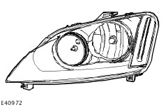
The headlamp units are primarily made of plastic and make use of free-form reflectors in order to optimise light distribution.
The transparent plastic cover is made of polycarbonate, and it is surface-hardened to protect it against scratches and cracks.
In the event of damage to the cover the entire headlamp unit needs to be replaced.
The turn signal lamps and side lights are also integrated in the headlamp unit.
The manual headlamp levelling system operates with an electric motor which is controlled via a rotary control in the instrument cluster.
For conventional headlamps, adapting the vehicle to conform to country-specific traffic situations (left/right-hand side traffic) during travel is accomplished by affixing punched adhesive strips to specific areas of the headlamp.
All conventional headlamps use 12 V bulbs with a spiral-wound filament.
NOTE:Certain safety measures need to be followed, as the circuits of the gas discharge headlamps may carry voltages of up to 30 kV.
High intensity discharge headlamps are optionally available.
A single xenon lamp located in the outer reflector generates a light beam which is used for both the dipped beam and the main beam.
In order to avoid dazzling oncoming traffic while driving with dipped beam, the light beam is modified by a masking screen which is inserted into the beam. An additional reflector is provided for the main beam, which is generated using a conventional bulb with a spiral-wound filament. This bulb is switched on when the headlamps are switched to main beam and when the headlamp flasher is operated.
The turn signal lamps and side lights are the same as in conventional headlamps.
In order to adapt the headlamps for driving on the opposite side of the road when driving abroad, a lever is provided at the rear of the headlamp which changes the shape of the light beam.
In order to prevent dazzling oncoming traffic, this lever moves a second masking screen into the light beam of the headlamp.
Headlamp levelling system
An automatic headlamp levelling system is a legal requirement for vehicles with gas discharge headlamps.
The automatic headlamp levelling system is a dynamic system which provides additional benefits for the driver in terms of improved illumination of the road due to improved control over the headlamp beam.
In a static system, the vehicle is only considered as a stationary object, whereas a dynamic system also takes into account the dynamic changes to the inclination of the vehicle whilst driving.
In order to prevent unnecessary changes in the height of the headlamp beam, the system filters out surface irregularities and any pitching of the vehicle under braking and acceleration.
The system is designed to respond to changes in the inclination of the vehicle caused by load changes or long-term effects of aerodynamic forces acting on the vehicle (e.g. due to continuous driving at high speeds).
Accordingly, the system needs to be set up with WDS after any components are replaced or any other repairs are carried out.
The front and rear sensors are Hall sensors which send a digital signal to the control unit.
Combined rain sensor/light sensor
CAUTION:On vehicles with autolamps, retrofitting with daytime running lamps is not permissible, as otherwise, the engine cannot be stopped when the lighting is switched on.
CAUTION:On vehicles with autolamps, the daytime running lamp fuse must not be fitted, as otherwise, the engine cannot be stopped when the lighting is switched on.
The combined rain sensor/light sensor is located behind the interior rear view mirror.
The ambient light sensor determines the general light intensity.
For this purpose, it records the light over as wide an angle as possible, without taking the direction of incidence into account.
The front light sensor determines the light intensity directly in front of the vehicle.
If both the ambient light sensor and the front light sensor detect a sudden reduction in light intensity at the same time, then an algorithm-based calculation is used to determine the fact that the vehicle has entered a tunnel, a multi-storey car park or a long underpass.
In this case, the request for switching on the exterior lighting and the indicator light in the instrument cluster is transmitted to the Generic Electronic Module (GEM).
If the vehicle enters into the shade thrown by a large truck, the two sensors will register different light intensities.. In this case, the algorithm-based calculation will not result in the lights being switched on.
In vehicles built from 10/2004, a stepped switch-off of the low beams, side lamps, license plate lamps as well as the instrument cluster and instrument panel illumination is implemented in the GEM. If the ambient light changes from dark to bright, the GEM first switches off the low beams. The side lamps, license plate lamps as well as the instrument cluster and instrument panel illumination are switched off approx. 6 seconds after the low beams have been switched off.
Automatic headlamps
2
-
External mirror housing
The GEM actuates the turn signal lamps and the side turn signal lamps.
The GEM sends a signal to the instrument cluster via the CAN bus to switch on the relevant turn indicator and the acoustic signal.
The signals from the hazard flasher switch and from the multifunction switch are transmitted to the GEM via a wiring connection.
The turn signals and the warning lamp flash at a specified frequency and, in the case of failure of a turn signal, the frequency is doubled.
The turn signal lamps also have a one-touch lane change function. If the multifunction switch is touched, the relevant turn signal is actuated 3 times by the GEM.
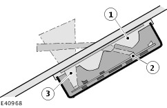
Door entry illumination
On some models, the door entry lamps are installed in the external mirrors.
The door entry lamps should illuminate the ground in the immediate vicinity of the front doors; they are equipped with white bulbs, which are installed in the underside of the mirror.
The door entry illumination is switched on when one of the doors or the tailgate are opened, or if an unlocking command is detected and the following conditions are satisfied:
- The ignition key is in position "0" or "I".
- Reverse gear is not engaged.
- The vehicle speed is below 7 km/h.
Rear lighting
The rear lamp clusters incorporate all of the rear lighting functions except the license plate lamp and the additional high-mounted stop lamp.
The rear lamp clusters are replaced as a complete unit in service.
The rear lamp cluster needs to be removed in order to change a bulb.
The individual bulb holders and circuits are integrated into the lamp holder.
A compact connector connects the lamp holder to the wiring harness.
The high-mounted additional stop lamp is installed in the middle of the tailgate.
Headlamp switch-off delay
In vehicles built from 10/2004 with mid to high-end equipment, the headlamp switch-off delay uses the low beams and the peripheral lights (if equipped) for illuminating the vehicle surroundings. The function is activated by operating the high beam lever when the ignition switch is in the "0" position.
After the last door has been closed, the function remains active for a further 30 seconds and then switches off automatically.
When a door or the tailgate is open, the switch-off time is extended to 180 seconds. After the last door has been closed, the switch-off time is reset to 30 seconds.
The headlamp switch-off delay can be deactivated prematurely by operating the high beam lever again or by switching on the ignition.
The switch-off time is adjusted to set values at the factory and cannot be re-programmed using WDS.