| Removal and Installation Wiring harness repair kit Hot air blower NOTE:Four M10 x 120 mm guide bolts are required for removing the dashboard together with the dashboard crossmember. All vehicles | | -
Raise the vehicle.
For additional information, refer to: Lifting (100-02 Jacking and Lifting, Description and Operation).
| | | -
Disconnect the connector of the rear left and right wheel sensors for the anti-lock brake system. - Unclip the wiring harness.
| | | -
Disconnect the rear bumper wiring harness electrical connector. - Unclip the wiring harness.
| | | -
Remove the metal clip of the rear right wheelhouse trim panel. - Slide the wheelhouse trim panel to one side.
| | | -
Disconnect the connector of the filler flap lock motor. - Unclip the wiring harness.
| | | -
Remove the right and left-hand front seats.
For additional information, refer to: Front Seat (501-10 Seating, Removal and Installation).
| | | -
Remove the center console extension.
For additional information, refer to: Floor Console Extension (501-12 Instrument Panel and Console, Removal and Installation).
| Vehicles built from 03/2007 NOTE:This operation is only required on vehicles with centre armrest. | | -
Remove the center console.
For additional information, refer to: Floor Console - Vehicles Built From: 03/2007, Vehicles With: Center Armrest (501-12 Instrument Panel and Console, Removal and Installation).
| | | -
Remove the gearshift console bracket. | All vehicles | | -
Remove the A-pillar trim on the right and left-hand sides.
For additional information, refer to: A-Pillar Trim Panel (501-05 Interior Trim and Ornamentation, Removal and Installation).
| | | -
Remove the B-pillar trim on the right and left-hand sides.
For additional information, refer to: B-Pillar Trim Panel (501-05 Interior Trim and Ornamentation, Removal and Installation).
| | | -
Remove the front rocker panel on the right and left hand sides.
For additional information, refer to: Front Scuff Plate Trim Panel (501-05 Interior Trim and Ornamentation, Removal and Installation).
| | | -
Remove the load space trim panels on the right and left-hand sides.
For additional information, refer to: Loadspace Trim Panel (501-05 Interior Trim and Ornamentation, Removal and Installation).
| | | -
Disconnect the connector of the fuel pump module. | | | -
Remove the right and left-hand rear lamp assemblies. | | | -
Disconnect the parking aid speaker electrical connector. | | | -
Remove the right and left-hand footwell trims (driver side shown). | Vehicles with automatic temperature control (EATC) | | -
Remove the audio unit. u29.3For additional information, refer to: (415-01 Audio Unit) Audio Unit (Removal and Installation), Audio Unit - Vehicles Built Up To: 01/2008, Vehicles With: Digital Versatile Disc (DVD) Navigation System (Removal and Installation), Audio Unit - Vehicles Built From: 01/2008, Vehicles With: Digital Versatile Disc (DVD) Navigation System (Removal and Installation). | Vehicles with manual temperature control | | -
Remove the climate control assembly.
For additional information, refer to: Climate Control Assembly - Vehicles With: Manual Temperature Control (412-04 Control Components, Removal and Installation).
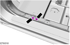
| 24. Remove the components in the order indicated in the following illustration(s) and table(s). 5 - Glove compartment screws 6 - Glove compartment light switch connector 7 - Glove compartment light connector 11 - Gearshift console reinforcing element bracket bolts 12 - Gearshift console reinforcing element bracket 13 - Gearshift console reinforcing element bolts 15 - Lower dashboard cover retaining bolts 17 - Data link connector (DLC) 18 - Front footwell air ducts 20 - Central junction box (CJB) bolts WARNING:Never perform work on the electric booster heater before the electric booster heater element has cooled to ambient temperature. Failure to observe this instruction can lead to injury. 22 - Electric booster heater ground connector (if fitted) 23 - Electric booster heater voltage supply connector with bracket (if fitted) 24 - Electric booster heater control wiring connector (if fitted) 25 - Remove the heater core upper cover bolts. 26 - Heater core upper cover 27 - Dashboard upper side trims 31 - Dashboard crossmember inner bolts 33 - Passenger-side dashboard wiring harness connector 34 - Driver-side dashboard wiring harness connector 35 - Dashboard wiring harness center connector 25. To install, reverse the removal procedure. Removal Details Item 2 : Door hinge bolts | | -
Support the door using a trolley jack with the aid of another technician. | Item 3 : Front doors (driver's door shown) | | -
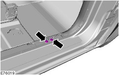
Detach the front door wiring harness connector from the A-pillar. | | | -
Detach the front door wiring harness connector. | Item 4 : Dashboard crossmember side bolts | | -
CAUTION:Do not remove the dashboard crossmember side bolts. Loosen the dashboard crossmember right and left-hand side bolts. | Item 8 : Glove compartment | | -
Disconnect passenger airbag deactivation (PAD) switch connector (if fitted). | Item 14 : Gearshift console reinforcing element | | -
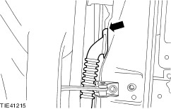
Remove the heater core / evaporator housing side bolt. | Item 29 : Stowage recess cover | | -
Fold up the stowage recess cover. | | | -
Remove the dashboard upper bolts. | | | -
Remove the steering column bracket upper bolts. | Item 30 : Dashboard crossmember outer bolts | | -
Support the heater housing with a wooden block. | | | -
Mark the position of the reinforcing element relative to the A-pillars (left-hand side shown). | | | -
After removing the outer bolts of the dashboard crossmember, screw in two M10 x 120 mm guide bolts each into the right and left-hand A-pillars (shown without dashboard for a clearer view). | Item 32 : Dashboard/dashboard crossmember | | -
Remove the right and left-hand side bolts of the dashboard crossmember. | | | -
Pull the dashboard forward to the stop together with the dashboard crossmember. | Item 36 : Dashboard/dashboard crossmember | | -
Disconnect the connector of the restraint control module (RCM). - Unclip the center console wiring harness and pull out under the carpet.
| | | -
Detach the steering column shaft joint from the steering column shaft. | | | -
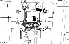
Detach the blower resistor connector (if fitted) and the blower motor connector. | | | -
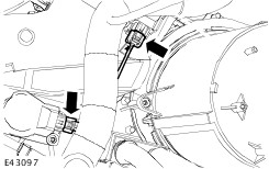
Detach the air recirculation flap actuator connector. | | | -
NOTE:Vehicles with EATC only Detach the right-hand temperature flap actuator connector and the defrost flap actuator connector. | | | -
NOTE:Vehicles with EATC only Detach the left-hand temperature flap actuator connector and the air distribution flap actuator connector. | | | -
NOTE:Vehicles with EATC only Detach the air outlet temperature sensor connector. | | | -
Disconnect the sun load sensor connector and the antenna cable connector. | | | -
Disconnect the roof console electrical connectors. | | | -
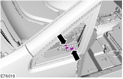
Remove the ground cable bolts. | | | -
Remove the ground cable bolts. | | | -
Remove the antenna cable from the clips on the dashboard crossmember. | | | -
Remove the right and left-hand M10 x 120 mm guide bolts. | Installation Details Item 37 : Passenger compartment wiring harness NOTE:Connect a new passenger compartment wiring harness to the disconnected connector of the fuel pump module. | | -
Disconnect the fuel pump module connector from the new wiring harness. | | | -
Remove the insulation at cable ends. | | | -
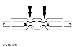
Insert the stripped ends of the wires into the crimp connector. - Stripped ends of the wires
- Crimp connector
| | | -
CAUTION:When crimping the connector ensure that the cross section of the connector matches that of the cable, and that the associated opening of the crimping pliers is used. NOTE:After crimping the connection, test it by performing a pull test. Crimp the connection with the crimping pliers. | | | -
NOTE:Using the hot air blower, heat the shrink sleeving of the crimp connector until the sleeving is tight on the connection and sealant emerges from each end. Heat the shrink sleeving. | Item 30 : Dashboard crossmember outer bolts | | -
Align the reinforcing element to the A-pillars (left-hand side shown). | Item 21 : Steering column shaft joint bolt WARNING:Install a new steering column shaft joint bolt. Failure to observe this instruction can lead to injury. Item 2 : Door hinge bolts | | -
Apply thread locking compound to the door hinge bolts. | |