| Diagnosis and Testing Refer to Wiring Diagrams Section 501-09, for schematic and connector information. Worldwide Diagnostic System (WDS) Inspection and Verification - Verify the customer concern.
- Visually inspect for obvious signs of mechanical or electrical damage.
Visual Inspection Chart | Mechanical | Electrical | | | - Fuse(s)
- Relay
- Electrical connector(s)
- Switch
| - If an obvious cause for an observed or reported concern is found, correct the cause (if possible) before proceeding to the next step.
- If the cause is not visually evident, verify the symptom and refer to the Symptom Chart.
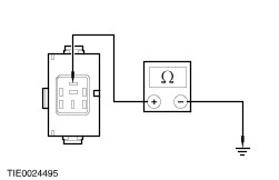
Symptom Chart | Symptom | Possible Sources | Action | | The mirrors are inoperative | * Exterior mirror control switch. * Circuit(s). | * REFER to WDS. | | A single mirror is inoperative | * Exterior mirror control switch. * Circuit(s). * Exterior mirror motor(s). | * REFER to WDS. | | A single mirror does not function with switch logic | * Exterior mirror control switch. * Circuit(s). * Exterior mirror motor(s). | * REFER to WDS. | | The heated exterior mirror does not defrost | * Heated rear window control switch. * Relay. * Circuit(s). * Heated mirror element(s). | * REFER to WDS. | | The power folding mirrors do not operate | * Power fold mirror control switch. * Circuit(s). | * | | The power folding mirrors do not operate correctly | * Power fold mirror(s). * Power fold mirror control switch. * Circuit(s). | * | | PINPOINT TEST A : THE POWER FOLDING MIRRORS DO NOT OPERATE | | TEST CONDITIONS | DETAILS/RESULTS/ACTIONS | | A1: CHECK THE POWER FOLDING MIRROR MODULE GROUND CIRCUIT FOR CONTINUITY | | | 1 Disconnect Power Folding Mirror Module C743. | | | 2 Measure the resistance between the power folding mirror module C743 pin 5, circuit 31-AD27 (BK), harness side and ground. | | | Is the resistance less than 5 ohms? Yes No REPAIR circuit 31-AD27 (BK). TEST the system for normal operation. | | A2: CHECK THE VOLTAGE TO THE POWER FOLDING MIRROR MODULE | | | 1 Measure the voltage between the power folding mirror module C743 pin 4, circuit 29-AD27 (OG/BK), harness side and ground. | | | Is the voltage greater than 10 volts? Yes No REPAIR circuit 29-AD27 (OG). TEST the system for normal operation. | | A3: CHECK FOR CONTINUITY BETWEEN THE POWER FOLDING MIRROR CONTROL SWITCH AND THE POWER FOLDING MIRROR MODULE | | | 1 Disconnect Power Fold Mirror Control Switch C222. | | | 2 Measure the resistance between the power folding mirror control switch C222 pin 2, circuit 91S-AD24 (BK/RD), harness side and the power folding mirror module C743 pin 2, circuit 31S-AD24 (BK/RD), harness side. | | | Is the resistance less than 5 ohms? Yes No REPAIR circuit 31S-AD24 (BK/RD) or circuit 91S-AD24 (BK/RD). TEST the system for normal operation. | | A4: CHECK FOR CONTINUITY BETWEEN THE POWER FOLDING MIRROR MODULE AND THE DRIVER POWER FOLDING MIRROR MOTOR | | | 1 Measure the resistance between the driver power folding mirror motor C807 pin 8, circuit 32-AD27 (WH/GN), harness side and the power folding mirror module C743 pin 3, circuit 32-AD27 (WH/GN), harness side. | | | Is the resistance less than 5 ohms? Yes No REPAIR circuit 32-AD27 (WH/GN). TEST the system for normal operation. | | A5: CHECK FOR CONTINUITY BETWEEN THE POWER FOLDING MIRROR MODULE AND THE DRIVER POWER FOLDING MIRROR MOTOR | | | 1 Measure the resistance between the driver power folding mirror motor C807 pin 9, circuit 33-AD27 (YE/GN), harness side and the power folding mirror module C743 pin 1, circuit 33-AD27 (YE/GN), harness side. | | | Is the resistance less than 5 ohms? Yes INSTALL a new power folding mirror module. TEST the system for normal operation. No REPAIR circuit 33-AD27 (YE/GN). TEST the system for normal operation. | | PINPOINT TEST B : THE POWER FOLDING MIRRORS DO NOT OPERATE CORRECTLY | | TEST CONDITIONS | DETAILS/RESULTS/ACTIONS | | B1: CHECK FOR CONTINUITY BETWEEN THE POWER FOLDING MIRROR MODULE AND THE INOPERATIVE POWER FOLDING MIRROR MOTOR | | | 1 Disconnect Inoperative Power Folding Mirror Motor C807 or C821. | | | 2 Disconnect Power Folding Mirror Module C743. | | | 3 Measure the resistance between the: - Driver power folding mirror - power folding mirror motor C807 pin 8, circuit 32-AD27 (WH/GN), harness side and the power folding mirror module C743 pin 3, circuit 32-AD27 (WH/GN), harness side.
- Passenger power folding mirror - power folding mirror motor C821 pin 8, circuit 32-AD28 (WH/GN), harness side and the power folding mirror module C743 pin 3, circuit 32-AD28 (WH/GN), harness side.
| | | Is the resistance less than 5 ohms? Yes No REPAIR circuit 32-AD27 (WH/GN) or circuit 32-AD28 (WH/GN). TEST the system for normal operation. | | B2: CHECK FOR CONTINUITY BETWEEN THE POWER FOLDING MIRROR MODULE AND THE INOPERATIVE POWER FOLDING MIRROR MOTOR | | | 1 Measure the resistance between the: - Driver power folding mirror - power folding mirror motor C807 pin 9, circuit 33-AD27 (YE/GN), harness side and the power folding mirror module C743 pin 1, circuit 33-AD27 (YE/GN), harness side.
- Passenger power folding mirror - power folding mirror motor C821 pin 9, circuit 33-AD28 (YE/GN), harness side and the power folding mirror module C743 pin 1, circuit 33-AD28 (YE/GN), harness side.
| | | Is the resistance less than 5 ohms? Yes INSTALL a new power folding exterior mirror.
REFER to: Exterior Mirror (501-09 Rear View Mirrors, Removal and Installation).
TEST the system for normal operation. No REPAIR circuit 33-AD27 (YE/GN) or circuit 33-AD28 (YE/GN). TEST the system for normal operation. | |