| Diagnosis and Testing Refer to Wiring Diagrams Section 501-09, for schematic and connector information. Inspection and Verification - Verify the customer concern.
- Visually inspect for obvious signs of mechanical or electrical damage.
Visual Inspection Chart | Mechanical | Electrical | - Exterior mirror(s)
- Auto-dimming interior mirror
| - Fuse(s)
- Relay
- Electrical connector(s)
- Exterior mirror control switch
- Heated rear window control switch
| - If an obvious cause for an observed or reported concern is found, correct the cause (if possible) before proceeding to the next step.
- If the cause is not visually evident, verify the symptom and refer to the Symptom Chart.
Symptom Chart Symptom Chart | Symptom | Possible Sources | Action | | The exterior mirrors are inoperative | * Exterior mirror control switch. | * CARRY OUT the Exterior Mirror Control Switch Component Test. REFER to the Wiring Diagrams. | | * Circuit(s). | * | | A single exterior mirror is inoperative | * Exterior mirror control switch. | * CARRY OUT the Exterior Mirror Control Switch Component Test. REFER to the Wiring Diagrams. | | * Exterior mirror motor(s). * Circuit(s). | * | | A single exterior mirror does not function with switch logic | * Exterior mirror control switch. | * CARRY OUT the Exterior Mirror Control Switch Component Test. REFER to the Wiring Diagrams. | | * Exterior mirror motor(s). * Circuit(s). | * | | The heated exterior mirror is inoperative | * Heated rear window control switch. | * CARRY OUT the Heated Rear Window Control Switch Component Test. REFER to the Wiring Diagrams. | | * Relay. * Heated mirror element(s). * Circuit(s). | * | | The auto-dimming interior mirror does not operate correctly | * Auto-dimming interior mirror. * Circuit(s). | * | Pinpoint Tests | PINPOINT TEST A : THE EXTERIOR MIRRORS ARE INOPERATIVE | NOTE:Use a digital multimeter for all electrical measurements. | | TEST CONDITIONS | DETAILS/RESULTS/ACTIONS | | A1: CHECK THE INTERIOR LAMP DELAY FUNCTION | | | 1 CHECK the interior lamp delay function. | | | Does the interior lamp delay function operate correctly? Yes No CHECK the battery saver relay operation.
REFER to: Interior Lighting (417-02 Interior Lighting, Diagnosis and Testing).
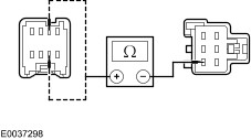
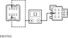
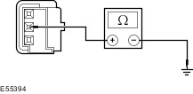
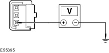
| | A2: CHECK THE VOLTAGE TO THE EXTERIOR MIRROR CONTROL SWITCH CIRCUIT | | | 1 Disconnect Exterior Mirror Control Switch C741. | | | 2 Ignition switch in position II. | | | 3 Measure the voltage between the exterior mirror control switch C741 pin 1, circuit 29-AD12 (OG/YE), harness side and ground. | | | Is the voltage greater than 10 volts? Yes No REPAIR circuit 29-AD12 (OG/YE). TEST the system for normal operation. | | A3: CHECK THE EXTERIOR MIRROR CONTROL SWITCH GROUND CIRCUIT FOR CONTINUITY | NOTE:The circuit number changes at soldered joint S197. | NOTE:The exterior mirror control switch and the driver side exterior window control switch have a common ground circuit. | | | 1 Ignition switch in position 0. | | | 2 Disconnect Driver Side Exterior Window Control Switch C488. | | | 3 Measure the resistance between the driver side exterior mirror control switch C488 pin 1, circuit 31-AJ7 (BK), harness side and ground. | | | Is the resistance less than 5 ohms? Yes VERIFY the customer concern. No REPAIR circuit 31-AJ7 (BK). TEST the system for normal operation. | | PINPOINT TEST B : A SINGLE EXTERIOR MIRROR IS INOPERATIVE | NOTE:Use a digital multimeter for all electrical measurements. | | TEST CONDITIONS | DETAILS/RESULTS/ACTIONS | | B1: CHECK FOR CONTINUITY BETWEEN THE EXTERIOR MIRROR CONTROL SWITCH AND THE INOPERATIVE EXTERIOR MIRROR | | | 1 Disconnect Exterior Mirror Control Switch C741. | | | 2 Disconnect Inoperative Exterior Mirror C808 or C822. | | | 3 Measure the resistance between the: Left-hand drive vehicles - Exterior mirror control switch C741 pin 7, circuit 32-AD6 (WH), harness side and the driver side exterior mirror C808 pin 3, circuit 32-AD6 (WH), harness side.
- Exterior mirror control switch C741 pin 3, circuit 32-AD9 (WH/GN), harness side and the passenger side exterior mirror C822 pin 3, circuit 32-AD9 (WH/GN), harness side.
| | | Is the resistance less than 5 ohms? Yes INSTALL a new exterior mirror.
REFER to: Exterior Mirror (501-09 Rear View Mirrors, Removal and Installation).
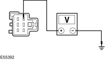
TEST the system for normal operation. No REPAIR circuit 32-AD6 (WH), or circuit 32-AD6C (WH), or circuit 32-AD9 (WH/GN) or circuit 32-AD9C (WH/GN). TEST the system for normal operation. | | PINPOINT TEST C : A SINGLE EXTERIOR MIRROR DOES NOT FUNCTION WITH SWITCH LOGIC | NOTE:Use a digital multimeter for all electrical measurements. | | TEST CONDITIONS | DETAILS/RESULTS/ACTIONS | | C1: CHECK THE EXTERIOR MIRROR FUNCTIONS WITH SWITCH LOGIC | | | 1 Ignition switch in position II. | | | 2 Operate the exterior mirror control switch. | | | Does the exterior mirror function with switch logic? Yes VERIFY the customer concern. No Driver side exterior mirror UP/DOWN inoperative - GO to C2. Driver side exterior mirror LEFT/RIGHT inoperative - GO to C5. Passenger side exterior mirror UP/DOWN inoperative - GO to C8. Passenger side exterior mirror LEFT/RIGHT inoperative - GO to C11. | | C2: CHECK THE DRIVER SIDE EXTERIOR MIRROR UP/DOWN CIRCUIT | | | 1 Ignition switch in position 0. | | | 2 Disconnect Driver Side Exterior Mirror C808. | | | 3 Ignition switch in position II. | | | 4 Select the driver side exterior mirror. While operating the exterior mirror control switch UP and DOWN, measure the voltage between the: | | | Left-hand drive vehicles - Driver side exterior mirror C808 pin 1, circuit 34-AD7 (BU/RD), harness side and the driver side exterior mirror C808 pin 3, circuit 32-AD6 (WH), harness side.
| | | Is the voltage greater than 10 volts when the exterior mirror control switch is moved to the UP position and is the polarity reversed when moved to the DOWN position? Yes INSTALL a new driver side exterior mirror.
REFER to: Exterior Mirror (501-09 Rear View Mirrors, Removal and Installation).
TEST the system for normal operation. No | | C3: CHECK CIRCUIT 34-AD7 (BU/RD) FOR CONTINUITY | | | 1 Ignition switch in position 0. | | | 2 Disconnect Exterior Mirror Control Switch C741. | | | 3 Measure the resistance between the: Left-hand drive vehicles - Exterior mirror control switch C741 pin 8, circuit 34-AD7 (BU/RD), harness side and the driver side exterior mirror C808 pin 1, circuit 34-AD7 (BU/RD), harness side.
| | | Is the resistance less than 5 ohms? Yes No REPAIR circuit 34-AD7 (BU/RD) or circuit 34-AD7C (BU/RD). TEST the system for normal operation. | | C4: CHECK CIRCUIT 32-AD6 (WH) FOR CONTINUITY | | | 1 Measure the resistance between the: Left-hand drive vehicles - Exterior mirror control switch C741 pin 7, circuit 32-AD6 (WH), harness side and the driver side exterior mirror C808 pin 3, circuit 32-AD6 (WH), harness side.
| | | Is the resistance less than 5 ohms? Yes INSTALL a new driver side exterior mirror.
REFER to: Exterior Mirror (501-09 Rear View Mirrors, Removal and Installation).
TEST the system for normal operation. No REPAIR circuit 32-AD6 (WH) or circuit 32-AD6C (WH). TEST the system for normal operation. | | C5: CHECK THE DRIVER SIDE EXTERIOR MIRROR LEFT/RIGHT CIRCUIT | | | 1 Ignition switch in position 0. | | | 2 Disconnect Driver Side Exterior Mirror C808. | | | 3 Ignition switch in position II. | | | 4 Select the driver side exterior mirror. While operating the exterior mirror control switch LEFT and RIGHT, measure the voltage between the: Left-hand drive vehicles - Driver side exterior mirror C808 pin 2, circuit 33-AD8 (YE/BU), harness side and the driver side exterior mirror C808 pin 3, circuit 32-AD6 (WH), harness side.
| | | Is the voltage greater than 10 volts when the exterior mirror control switch is moved to the LEFT position and is the polarity reversed when moved to the RIGHT position? Yes INSTALL a new driver side exterior mirror.
REFER to: Exterior Mirror (501-09 Rear View Mirrors, Removal and Installation).
TEST the system for normal operation. No | | C6: CHECK CIRCUIT 33-AD8 (YE/BU) FOR CONTINUITY | | | 1 Ignition switch in position 0. | | | 2 Disconnect Exterior Mirror Control Switch C741. | | | 3 Measure the resistance between the: Left-hand drive vehicles - Exterior mirror control switch C741 pin 6, circuit 33-AD8 (YE/BU), harness side and the driver side exterior mirror C808 pin 2, circuit 33-AD8 (YE/BU), harness side.
| | | Is the resistance less than 5 ohms? Yes No REPAIR circuit 33-AD8 (YE/BU) or circuit 33-AD8C (YE/BU). TEST the system for normal operation. | | C7: CHECK CIRCUIT 32-AD6 (WH) FOR CONTINUITY | | | 1 Measure the resistance between the: Left-hand drive vehicles - Exterior mirror control switch C741 pin 7, circuit 32-AD6 (WH), harness side and the driver side exterior mirror C808 pin 3, circuit 32-AD6 (WH), harness side.
| | | Is the resistance less than 5 ohms? Yes INSTALL a new driver side exterior mirror.
REFER to: Exterior Mirror (501-09 Rear View Mirrors, Removal and Installation).
TEST the system for normal operation. No REPAIR circuit 32-AD6 (WH) or circuit 32-AD6 (WH). TEST the system for normal operation. | | C8: CHECK THE PASSENGER SIDE MIRROR UP/DOWN CIRCUIT | | | 1 Ignition switch in position 0. | | | 2 Disconnect Passenger Side Exterior Mirror C822. | | | 3 Ignition switch in position II. | | | 4 Select the passenger side exterior mirror. While operating the exterior mirror control switch UP and DOWN, measure the voltage between the passenger side exterior mirror C822 pin 1, circuit 34-AD10 (BU/YE), harness side and the passenger side exterior mirror C822 pin 3, circuit 32-AD9 (WH/GN), harness side. | | | Is the voltage greater than 10 volts when the exterior mirror control switch is moved to the UP position and is the polarity reversed when moved to the DOWN position? Yes INSTALL a new passenger side exterior mirror.
REFER to: Exterior Mirror (501-09 Rear View Mirrors, Removal and Installation).
TEST the system for normal operation. No | | C9: CHECK CIRCUIT 34-AD10 (BU/YE) FOR CONTINUITY | | | 1 Ignition switch in position 0. | | | 2 Disconnect Exterior Mirror Control Switch C741. | | | 3 Measure the resistance between the: Left-hand drive vehicles - Exterior mirror control switch C741 pin 4, circuit 34-AD10 (BU/YE), harness side and the passenger side exterior mirror C822 pin 1, circuit 34-AD10 (BU/YE), harness side.
| | | Is the resistance less than 5 ohms? Yes No REPAIR circuit 34-AD10 (BU/YE) or circuit 34-AD10C (BU/YE). TEST the system for normal operation. | | C10: CHECK CIRCUIT 32-AD9 (WH/GN) FOR CONTINUITY | | | 1 Measure the resistance between the: Left-hand drive vehicles - Exterior mirror control switch C741 pin 3, circuit 32-AD9 (WH/GN), harness side and the passenger side exterior mirror C822 pin 3, circuit 32-AD9 (WH/GN), harness side.
| | | Is the resistance less than 5 ohms? Yes INSTALL a new passenger side exterior mirror.
REFER to: Exterior Mirror (501-09 Rear View Mirrors, Removal and Installation).
TEST the system for normal operation. No REPAIR circuit 32-AD9 (WH/GN) or circuit 32-AD9C (WH/GN). TEST the system for normal operation. | | C11: CHECK THE PASSENGER SIDE EXTERIOR MIRROR LEFT/RIGHT CIRCUIT | | | 1 Ignition switch in position 0. | | | 2 Disconnect Passenger Side Exterior Mirror C822. | | | 3 Ignition switch in position II. | | | 4 Select the passenger side exterior mirror. While operating the exterior mirror control switch LEFT and RIGHT, measure the voltage between the passenger side exterior mirror C822 pin 2, circuit 33-AD11 (YE/VT), harness side and the passenger side exterior mirror C822 pin 3, circuit 32-AD9 (WH/GN), harness side. | | | Is the voltage greater than 10 volts when the exterior mirror control switch is moved to the LEFT position and is the polarity reversed when moved to the RIGHT position. Yes INSTALL a new passenger side exterior mirror.
REFER to: Exterior Mirror (501-09 Rear View Mirrors, Removal and Installation).
TEST the system for normal operation. No | | C12: CHECK CIRCUIT 33-AD11 (YE/VT) FOR CONTINUITY | | | 1 Ignition switch in position 0. | | | 2 Disconnect Exterior Mirror Control Switch C741. | | | 3 Measure the resistance between the: Left-hand drive vehicles - Exterior mirror control switch C741 pin 2, circuit 33-AD11 (YE/VT), harness side and the passenger side exterior mirror C822 pin 2, circuit 33-AD11 (YE/VT), harness side.
| | | Is the resistance less than 5 ohms? Yes No REPAIR circuit 33-AD11 (YE/VT) or circuit 33-AD11C (YE/VT). TEST the system for normal operation. | | C13: CHECK CIRCUIT 32-AD9 (WH/GN) FOR CONTINUITY | | | 1 Measure the resistance between the: Left-hand drive vehicles - Exterior mirror control switch C741 pin 3, circuit 32-AD9 (WH/GN), harness side and the passenger side exterior mirror C822 pin 3, circuit 32-AD9 (WH/GN), harness side.
| | | Is the resistance less than 5 ohms? Yes INSTALL a new passenger side exterior mirror.
REFER to: Exterior Mirror (501-09 Rear View Mirrors, Removal and Installation).
TEST the system for normal operation. No REPAIR circuit 32-AD9 (WH/RD) or circuit 32-AD9C (WH/RD). TEST the system for normal operation. | | PINPOINT TEST D : THE HEATED EXTERIOR MIRROR IS INOPERATIVE | NOTE:Use a digital multimeter for all electrical measurements. | | TEST CONDITIONS | DETAILS/RESULTS/ACTIONS | | D1: CHECK THE OPERATION OF THE HEATED REAR WINDOW | | | 1 Ignition switch in position II. | | | 2 Operate the heated rear window control switch. | | | Does the heated rear window function correctly? Yes No REPAIR the heated rear window. REFER to: Glass, Frames and Mechanisms - Vehicles With: Front Power Windows (501-11, Diagnosis and Testing), Glass, Frames and Mechanisms - Vehicles With: Front and Rear Power Windows (501-11 Glass, Frames and Mechanisms, Diagnosis and Testing). | | D2: CHECK THE VOLTAGE TO THE INOPERATIVE EXTERIOR MIRROR | | | 1 Ignition switch in position 0. | | | 2 Disconnect Inoperative Exterior Mirror C808 or C822. | | | 3 Ignition switch in position II. | | | 4 Operate the heated rear window control switch. | | | 5 Measure the voltage between the: - Driver side exterior mirror C808 pin 4, circuit 15S-HB35 (GN/BK), harness side and ground.
- Passenger side exterior mirror C822 pin 4, circuit 15S-HB36 (GN/OG), harness side and ground.
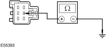
| | | Is the voltage greater than 10 volts? Yes No REPAIR circuit 15S-HB35 (GN/BK) or circuit 15S-HB36 (GN/OG). TEST the system for normal operation. | | D3: CHECK THE INOPERATIVE EXTERIOR MIRROR GROUND CIRCUIT FOR CONTINUITY | | | 1 Ignition switch in position 0. | | | 2 Measure the resistance between the: - Driver side exterior mirror C808 pin 5, circuit 31-HB35 (BK), harness side and ground.
- Passenger side exterior mirror C822 pin 5, circuit 31-HB36 (BK), harness side and ground.
| | | Is the resistance less than 5 ohms? Yes INSTALL a new heated exterior mirror glass. TEST the system for normal operation. No REPAIR circuit 31-HB35 (BK) or circuit 31-HB36 (BK). TEST the system for normal operation. | | PINPOINT TEST E : THE AUTO-DIMMING INTERIOR MIRROR DOES NOT OPERATE CORRECTLY | NOTE:Use a digital multimeter for all electrical measurements. | | TEST CONDITIONS | DETAILS/RESULTS/ACTIONS | | E1: CHECK FOR CONTINUITY BETWEEN THE AUTO-DIMMING INTERIOR MIRROR AND GROUND | | | 1 Disconnect Auto-dimming Interior Mirror C742. | | | 2 Measure the resistance between the auto-dimming interior mirror C742 pin 2, circuit 91-AD15 (BK/OG), harness side and ground. | | | Is the resistance less than 5 ohms? Yes No REPAIR circuit 91-AD15 (BK/OG). TEST the system for normal operation. | | E2: CHECK THE VOLTAGE TO THE AUTO-DIMMING INTERIOR MIRROR | | | 1 Ignition switch in position II. | | | 2 Measure the voltage between the auto-dimming interior mirror C742 pin 1, circuit 29-AD15 (OG), harness side and ground. | | | Is the voltage greater than 10 volts? Yes No REPAIR circuit 29-AD15 (OG). TEST the system for normal operation. | | E3: CHECK THE REVERSE CUT-OUT VOLTAGE TO THE AUTO-DIMMING INTERIOR MIRROR | | | NOTE:Make sure the selector lever is in the 'N' (NEUTRAL) position. 1 Measure the voltage between the auto-dimming interior mirror C742 pin 3, circuit 15S-AD15 (GN/RD), harness side and ground. | | | Is any voltage present? Yes No | | E4: CHECK FOR VOLTAGE TO THE AUTO-DIMMING INTERIOR MIRROR | | | 1 Ignition switch in position 0. | | | 2 Disconnect Transmission Switch C864 or Transmission Switch C866 or Reversing Lamps Relay C1003. | | | 3 Ignition switch in position II. | | | 4 Measure the voltage between the auto-dimming interior mirror C742 pin 3, circuit 15S-AD15 (GN/RD), harness side and ground. | | | Is any voltage present? Yes INSTALL a new transmission switch or reversing lamp relay. TEST the system for normal operation. No REPAIR circuit 15S-AD15 (GN/RD). TEST the system for normal operation. | | E5: CHECK THE REVERSE CUT-OUT VOLTAGE TO THE AUTO-DIMMING INTERIOR MIRROR | | | 1 Select R (REVERSE). | | | 2 Measure the voltage between the auto-dimming interior mirror C742 pin 3, circuit 15S-AD15 (GN/RD), harness side and ground. | | | Is the voltage greater than 10 volts? Yes INSTALL a new auto-dimming interior mirror.
REFER to: Auto-dimming Interior Mirror (501-09 Rear View Mirrors, Removal and Installation).
TEST the system for normal operation. No REPAIR circuit 15S-AD15 (GN/RD). TEST the system for normal operation. | |