
Crown Victoria V8-4.6L SOHC VIN 6 (1996)
NOTE:
DEPTH OF CUT SHOULD BE BETWEEN 0.10 AND O.2O mm (0.004 AND 0.008"). LIGHTER CUTS WILL CAUSE THE BIT TO HEAT UP A
d.
Center cutting head, adjust cutting bits, install chip deflector.
e.
Machine rotor.
f.
Measure and record rotor thickness.
NOTE:
TARGET LRO IS 0.000 mm, MAXIMUM IS O.05 mm (0.002").
g.
Install dial indicator, measure and record rotor LRO. Remove dial indicator.
h.
Remove lathe and silencer belt.
10.
Remove metal shavings.
11.
Remove the adapter.
12.
For vehicles with two-piece hub/rotors:
a.
Remove rotor from hub.
b.
Remove metal shavings from hub and rotor mounting surfaces and from ABS sensors.
c.
Apply High Temperature Nickel Anti-Seize Lubricant (F6AZ-9L494-AA) to hub mounting surface to prevent future corrosion.
d.
Match marks on rotor and hub and assemble rotor to hub.
13.
Install pads and calipers.
NOTE:
USING AN IMPACT TOOL WITHOUT AN ACCUTORO(R) SOCKET WILL LEAD TO UNEVENLY TORQUED LUG NUTS. THIS CAUSES R
14.
Install wheels using impact guns equipped with Rotunda AccuTorq(R) sockets. Use a torque wrench on locking lug nuts.
15.
Check brake operation before returning to customer.
Support Telephone Numbers
1.
Lathe Administration Support: (800) 768-8632
2.
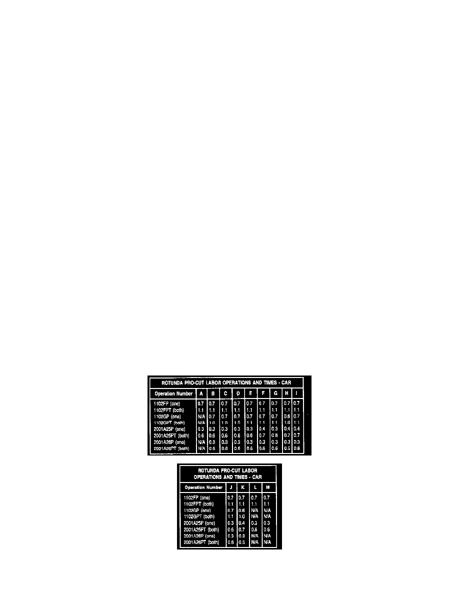
Pro-Cut Technical Support: (800) 543-6618 Reference list for Pro-Cut car labor operations: