
Crown Victoria V8-4.6L SOHC VIN 6 (1996)
22. Raise vehicle.
23. Connect EVO sensor and oil sending unit.
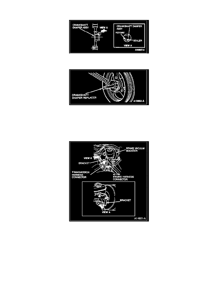
24. Apply Silicone Gasket and Sealant F1AZ-19562-A (WSE-M4G320-A2) or equivalent in keyway of damper as shown.
25. Position damper on crankshaft. Ensure crankshaft key and keyway are aligned.
26. Using Crankshaft Damper Replacer T74P-6316-B, install crankshaft damper.
27. Install damper bolt and washer. Tighten to 155-165 N-m (114-121 lb-ft).
28. Install four bolts retaining oil pan to front cover. Tighten to 20-30 N-m (15-22 lb-ft).
29. Position power steering pump on engine and install four retaining bolts. Tighten to 20-30 N-m (15-22 lb-ft).
30. Lower vehicle.
31. Connect air conditioning compressor, HDR sensor and canister purge solenoid.
32. Connect 42-pin engine harness connector and transmission harness connector.
33. Install 42-pin connector on retaining bracket on vacuum brake booster.
34. Install PCV valve in RH camshaft cover and connect canister purge solenoid vent hose.
35. Position positive battery cable harness on RH cylinder head.
36. Install bolt retaining cable bracket to cylinder head.
37. Connect vent hose to canister purge solenoid.
38. Connect positive battery cable at power distribution box and battery.
39. Install water pump pulley and tighten bolts to 20-30 N-m (15-22 lb-ft).
40. Position ignition coil brackets and ignition wire assembly onto mounting studs.
41. Install seven nuts retaining coil brackets to front cover. Tighten to 20-30 N-m (15-22 lb-ft).
42. Connect both ignition coils and CID sensor.
43. Position air conditioner high pressure line on RH coil bracket and install bolt.