
Crown Victoria V8-4.6L SOHC VIN 6 (1996)
Courtesy Lamps Symptom Chart (1 Of 2)
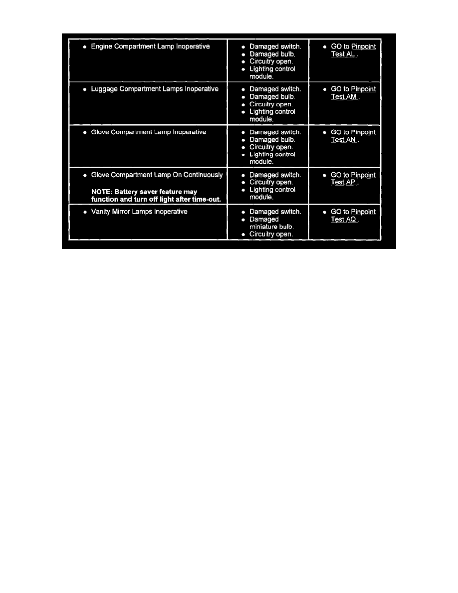
Courtesy Lamps Symptom Chart (2 Of 2)
BA - No Communication With Lighting Control Module (LCM)
Pinpoint Test BA: No Communication With Lighting Control Module
BA1 - Check Circuit 195 (T/W) For Power
-
Disconnect lighting control module connector C3.
-
USing a voltmeter, measure for voltage at lighting control module connector pin C3-6, circuit 195 (T/W).
Is voltage B+?
YES
GO to BA5.
NO
GO to BA2.
BA2 - Check Circuit 195 (T/W) For Short To Ground
-
Remove fuse 4 (15A) from fuse junction panel.
-
Using an ohmmeter connected to ground, measure resistance at lighting control module connector pin C3-6 circuit 195 (T/W).
IS resistance less than 10K ohms?
YES
SERVICE circuit 195 (T/W) for short to ground. REPLACE fuse 4 (15A). RESTORE vehicle. RETEST system.
NO
GO to BA3.
BA3 - Check Supply To Fuse 4 (15A)
-
Remove fuse 4 (15A) from fuse junction panel.
-
Using a voltmeter, measure for voltage at fuse 4 input cavity.
Is voltage B+?
YES
GO to BA4.
NO
SERVICE supply to fuse 4 (15A). RESTORE vehicle. RETEST system.
BA4 - Check Circuit 195 (T/W) For Open