
Engine
- Make
- Ford
- Model
- Crown Victoria Factory Service Manual
- Year
- 2007
- Section
- 303-01 Engine › Removal › Engine
EngineEngine
Engine
 |
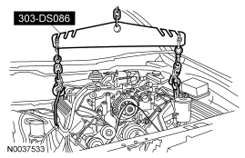
Lifting Bracket Set, Engine
303-DS086 (D93P-6001-A) |
 |
Socket, Exhaust Gas Oxygen Sensor
303-476 (T94P-9472-A) |
-
WARNING: If equipped with fire suppression system, depower the system. For important safety warnings and procedures, refer to Section 419-03.
With the vehicle in NEUTRAL, position it on a hoist. For additional information refer to Section 100-02. - Release the fuel pressure. For additional information, refer to Section 310-00.
- Remove the hood.
- Disconnect both battery cables. For additional information, refer to Section 414-01.
- Remove the air cleaner and outlet pipe. For additional information, refer to Section 303-12.
- Remove the wiper mounting arm and pivot shaft. For additional information, refer to Section 501-16.
- Remove the 2 nuts and the support bracket.
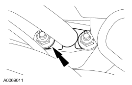
- Remove the accessory drive belt. For additional information, refer to Section 303-05.
- Drain the engine cooling system. For additional information, refer to Section 303-03.
- Disconnect the vacuum hose.
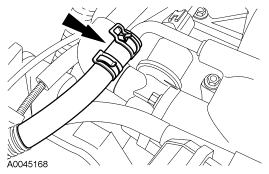
- Disconnect the evaporative emission (EVAP) canister purge valve.
- Disconnect the 2 quick release EVAP hoses.
- Disconnect the electrical connector.
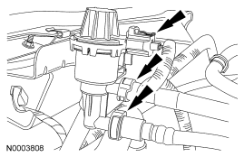
- Disconnect the fuel tube spring lock coupling. For additional information, refer to Section 310-00.
- Detach the generator battery cable retainer from the RH valve cover stud bolt.
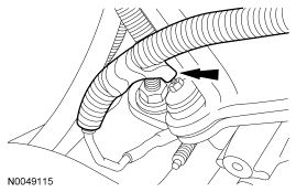
- Remove the nut and disconnect the generator battery cable.
- Detach the generator battery cable pin-type retainer.
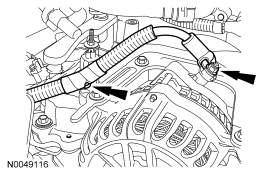
- Disconnect the PCM electrical connectors.
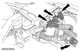
- Disconnect the ground wire.
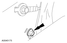
- Disconnect the A/C electrical connector.
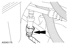
- Disconnect the A/C low charge protection switch electrical connector.
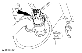
- Disconnect the heater hoses.
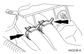
- Remove the ground strap.
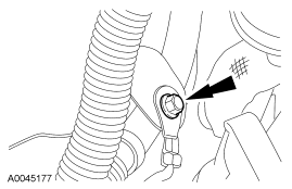
- Disconnect the upper radiator hose from the hose connection. Secure the hose to the radiator assembly.
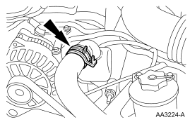
- Disconnect the lower radiator hose from the oil filter adapter.
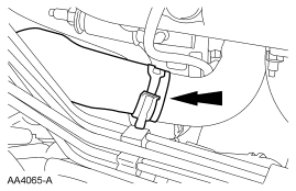
- Remove the cooling fan. For additional information, refer to Section 303-03.
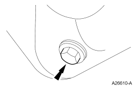
- Drain the engine oil.
- Install the drain plug when finished.
- To install, tighten to 13 Nm (10 lb-ft).
- If equipped, disconnect the block heater electrical connector.
- Disconnect the power steering electrical connector.
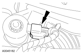
- Disconnect the oil pressure sender electrical connector.
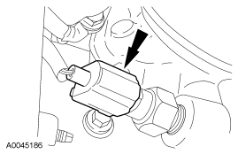
- Disconnect the power steering pressure (PSP) switch electrical connector.
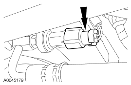
-
CAUTION: The oil cooler must be replaced or severe damage to the engine can occur.
If equipped, remove and discard the oil cooler. For additional information, refer to Oil Cooler in this section. - Remove the nut and the transmission cooler tube support bracket.
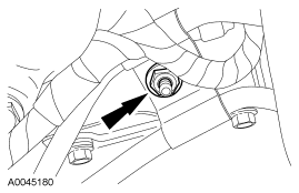
- Remove the bolt.
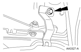
- Disconnect the crankshaft position (CKP) sensor electrical connector.
- Position the power steering tube bracket aside.
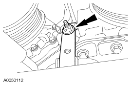
- Disconnect the engine wiring harness retainers from the A/C compressor.
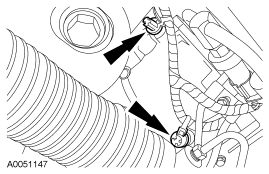
- Disconnect the A/C compressor electrical connector.
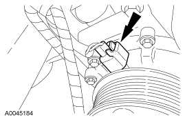
- Remove the 3 bolts and position the A/C compressor aside.
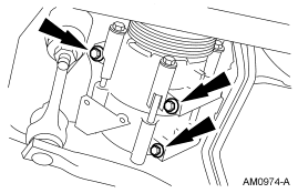
- Remove the 4 bolts and position the power steering pump aside.
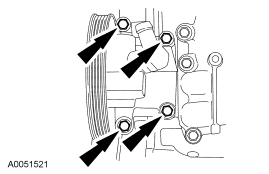
- Remove the starter motor.
- Remove the starter motor solenoid cover.
- Disconnect the electrical connections.
- Remove the bolts.
- Remove the starter motor.
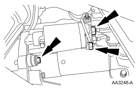
- Disconnect the RH heated oxygen sensor (HO2S) electrical connectors.
- Disconnect the LH HO2S electrical connector.
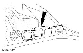
- Using the special tool, remove the LH HO2S.
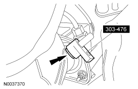
- Support the exhaust and remove the 4 nuts.
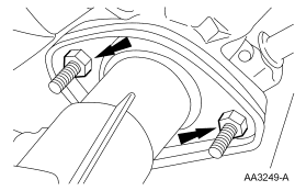
-
NOTE: LH shown, RH similar.
Remove the 2 engine mount nuts.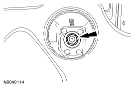
- Install a suitable lifting device under the transmission and support.
- Remove the rear transmission insulator nuts.
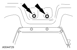
- Raise the transmission and remove the rear transmission insulator bolts.
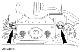
- Remove the transmission rear insulator and lower the transmission down to rest on the rear crossmember.
- Disconnect the HO2S sensor and the solenoid body sensor electrical connectors.
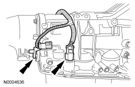
- Disconnect the output shaft speed sensor, transmission range sensor and the turbine shaft speed sensor electrical connectors.
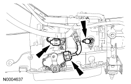
- Release the wiring harness from the retainers on the transmission.
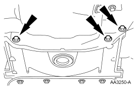
- Remove the 3 bolts and the inspection cover.
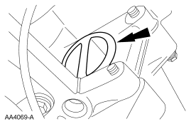
- Remove the torque converter nut access plug.
- Remove the 4 nuts.
- Remove the 4 bolts and 1 stud.
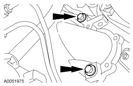
- Remove the engine support insulator nuts.
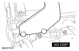
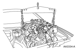
- Install the special tool to the RH cylinder head.
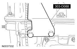
- Install the special tool to the LH cylinder head.
- Install the special tools.
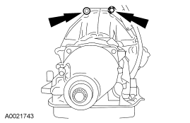
- Remove the 2 bolts.
- Remove the engine assembly from the vehicle.
Parts & tools for this job For 2007 Ford Crown Victoria
- PARTEngine gasket setSearch: Ford Crown Victoria 2007 engine gasket set
- TOOLTorque wrenchSearch: 3/8 inch torque wrench
- TOOLFeeler gauge setSearch: feeler gauge set
Links open Amazon search results in a new tab. As an Amazon Associate I earn from qualifying purchases.