
E 450 V8-5.4L (2009)
Interior Lighting
Pinpoint Tests
Pinpoint Test D: All The Courtesy Lamps Stay On Continuously
Refer to Wiring Diagram Set 89, Interior Lamps for schematic and connector information. See: Diagrams/Electrical Diagrams/Diagrams By Number
Refer to Wiring Diagram Set 117, Remote Keyless Entry and Alarm for schematic and connector information. See: Diagrams/Electrical
Diagrams/Diagrams By Number
Normal Operation
The Smart Junction Box (SJB) sends a voltage reference signal to the door ajar switches through circuits CPL26 (GN/VT) (LH front door), CPL31
(WH) (RH front door), CPL36 (GN) (side door or body builder connector for cutaway vehicles) and CPL39 (YE) (RH rear door). Ground is provided to
the LH front and rear door ajar switches through circuit GD133 (BK), the RH front ajar switch through circuit GD116 (BK/VT) and the side door
through circuit GD115 (BK/GY). The door ajar switch is open with the door closed. When the door is opened, the signal to ground is completed,
indicating an open door to the SJB.
The SJB also monitors the instrument panel dimmer switch status from circuit CLN28 (GN/BU) to determine if the courtesy lamps are requested. When
the instrument panel dimmer switch is rotated to the DOME LAMP position, ground is supplied to circuit CLN28 (GN/BU).
When the request from the instrument panel dimmer switch is detected, any door is opened or an unlock request from a programmed Remote Keyless
Entry (RKE) transmitter is detected, the SJB supplies voltage to the interior courtesy lamps through circuit VLN33 (GY/VT).
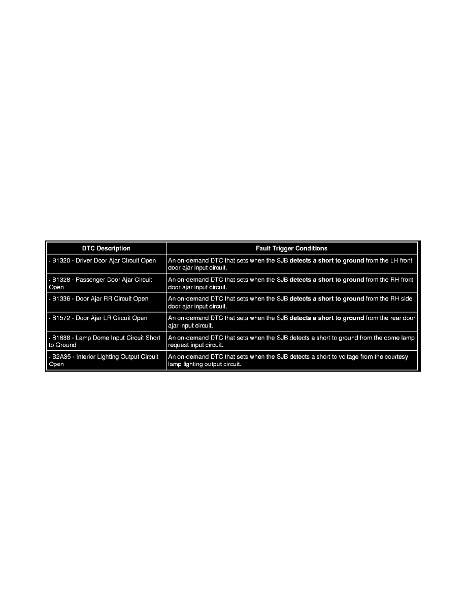
B2A35-B1688
This pinpoint test is intended to diagnose the following:
-
Wiring, terminals or connectors
-
Door ajar switch
-
Instrument panel dimmer switch
-
Body builder equipment
-
SJB
PINPOINT TEST D: ALL THE COURTESY LAMPS STAY ON CONTINUOUSLY
NOTICE: Use the correct probe adapter(s) when making measurements. Failure to use the correct probe adapter(s) may damage the
connector.
-------------------------------------------------
D1 CHECK FOR SJB OUTPUT DTCs
-
Ignition OFF.