
E 450 V8-5.4L (2009)
-
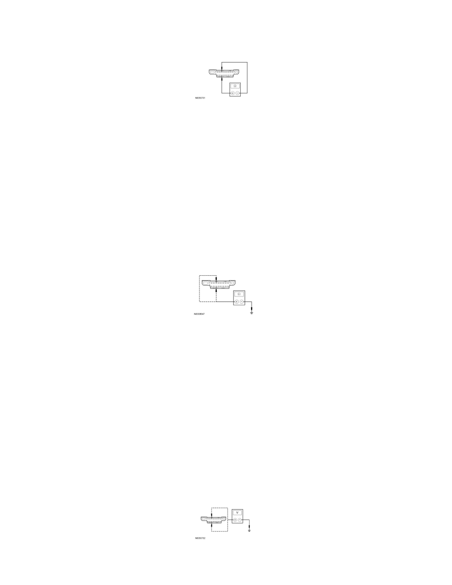
Disconnect: Negative Battery Cable.
-
Measure the resistance between the DLC C251-3, circuit VDB06 (GY/OG), harness side and the DLC C251-11, circuit VDB07 (VT/OG), harness
side.
-
Is the resistance between 54 and 66 ohms?
Yes
GO to J3.
No
CONNECT the negative battery cable. Go To Pinpoint Test I. See: Pinpoint Test I: No Medium Speed Controller Area Network (MS-CAN)
Communication, All Modules Are Not Responding
-------------------------------------------------
J3 CHECK THE MS-CAN (+) AND MS-CAN (-) CIRCUITS FOR A SHORT TO
GROUND
-
Measure the resistance between the DLC C251-3, circuit VDB06 (GY/OG), harness side and ground; and between the DLC C251-11, circuit
VDB07 (VT/OG), harness side and ground.
-
Are the resistances greater than 1,000 ohms?
Yes
CONNECT the negative battery cable. GO to J4.
No
CONNECT the negative battery cable. Go To Pinpoint Test I. See: Pinpoint Test I: No Medium Speed Controller Area Network (MS-CAN)
Communication, All Modules Are Not Responding
-------------------------------------------------
J4 CHECK THE MS-CAN (+) AND MS-CAN (-) CIRCUITS FOR A SHORT TO
VOLTAGE
-
Ignition ON.
-
Measure the voltage between the DLC C251-3, circuit VDB06 (GY/OG), harness side and ground; and between the DLC C251-11, circuit VDB07
(VT/OG), harness side and ground.
-
Is the voltage greater than 6 volts on either circuit?