
E 450 V8-5.4L (2009)
No
CONNECT all modules. CONNECT the negative battery cable. GO to K27.
-------------------------------------------------
K17 CHECK THE HS-CAN (+) AND HS-CAN (-) CIRCUITS FOR A SHORT TO GROUND
WITH THE PCM DISCONNECTED
-
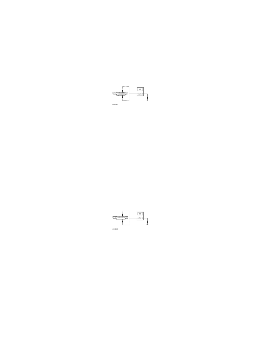
Disconnect: PCM C175b or C1381b.
-
Measure the resistance between the DLC C251-6, circuit VDB04 (WH/BU), harness side and ground; and between the DLC C251-14, circuit
VDB05 (WH), harness side and ground.
-
Are the resistances greater than 1,000 ohms?
Yes
CONNECT the negative battery cable. GO to K23.
No
If the vehicle is equipped with a telematics module, GO to K18. If the vehicle is not equipped with a telematics module, GO to K19.
-------------------------------------------------
K18 CHECK THE HS-CAN (+) AND HS-CAN (-) CIRCUITS FOR A SHORT TO GROUND
WITH THE TELEMATICS MODULE DISCONNECTED
-
Disconnect: Telematics Module C2409.
-
Measure the resistance between the DLC C251-6, circuit VDB04 (WH/BU), harness side and ground; and between the DLC C251-14, circuit
VDB05 (WH), harness side and ground.
-
Is the resistance less than 5 ohms?
Yes
CONNECT the negative battery cable. GO to K28.
No
GO to K19.
-------------------------------------------------
K19 CHECK THE HS-CAN (+) AND HS-CAN (-) CIRCUITS FOR A SHORT TO GROUND
WITH THE ABS MODULE DISCONNECTED
-
Disconnect: ABS Module C135 or C155.
-
Measure the resistance between the DLC C251-6, circuit VDB04 (WH/BU), harness side and ground; and between the DLC C251-14, circuit
VDB05 (WH), harness side and ground.