
E 450 V8-5.4L (2009)
-
Do not allow the clockspring rotor to turn.
Installing clockspring requiring recentering
2. WARNING: If the clockspring is not correctly centralized, it may fail prematurely. If in doubt, repeat the centralizing procedure. Failure
to follow these instructions may increase the risk of serious personal injury or death in a crash.
NOTICE: To prevent damage to the clockspring, make sure the road wheels are in the straight-ahead position.
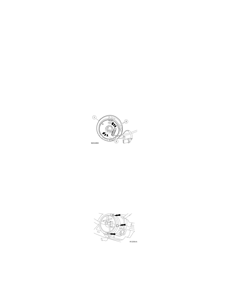
NOTE: The clockspring inner rotor, wiring and connector must be in the 12 o'clock position to install the steering wheel.
If the vehicle clockspring has rotated out of center, follow these steps to center the clockspring.
1. Hold the clockspring outer housing stationary.
2. NOTICE: Do not over-rotate the clockspring inner rotor. The internal ribbon wire is connected to the clockspring rotor. The internal
ribbon wire acts as a stop and can be broken from its internal connection. Failure to follow this instruction may result in component
damage and/or system failure.
While turning the rotor clockwise, carefully feel for the ribbon wire to run out of length and for a slight resistance. Stop turning at this point.
3. Turn the clockspring counterclockwise approximately 2.25 turns. This is the center point of the clockspring.
-
Do not allow the rotor to turn from this position.
Installing original clockspring
3. NOTE: When the tape is removed, do not allow the clockspring to turn.
Remove the tape applied during clockspring removal.
All clocksprings
4. NOTE: Slight turning of the clockspring rotor is allowable for alignment purposes to the steering column.
With the flats of the clockspring rotor aligned to the flats of the steering column shaft, slide the clockspring onto the steering column engaging the
retaining tabs.
5. Press at the 6, 12 and 3 o'clock positions to seat the clockspring.
6. Route the clockspring wiring through the instrument panel.
7. Attach the 2 clockspring retaining clips holding the wire to the steering column.
8. If equipped, install the key-in-ignition warning indicator switch.