
Econoline E350 1 Ton V8-5.4L Prop SOHC VIN Z (1998)
Rotate the steering wheel to the RH stop. then turn the steering wheel 90° back from that position. Turn the steering wheel slowly in a 15° to 30°
arc.
4.
Turn the steering wheel another 90°. Turn the steering wheel slowly in a 15° to 30° arc.
5.
Repeat the test with power steering fluid at different temperatures.
6.
If a light grunt is heard or a low (50-200Hz) shudder is present, this is a normal steering system condition.
Checking Tooth Contact Pattern/Condition of Ring & Pinion
There are two basic types of conditions that will produce ring and pinion noise. The first type is a howl or chuckle produced by broken, cracked,
chipped, scored or forcibly damaged gear teeth and is usually quite audible over the entire speed range. The second type of ring and pinion noise pertains
to the mesh pattern of the gear pattern. This gear noise can be recognized as it produces a cycling pitch or whine. Ring and pinion noise tends to peak in
a narrow speed range or ranges, and will tend to remain constant in pitch.
1.
Raise and support the vehicle.
2.
Drain the axle lubricant. Refer to the appropriate workshop manual for the draining procedures.
3.
Remove the carrier assembly or the axle housing cover depending on the axle type. Refer to the appropriate workshop manual for the service
procedures.
4.
Inspect the gear set for scoring or damage.
5.
In the following steps, the movement of the contact pattern along the length is indicated as toward the "heel" or "toe" of the differential ring gear.
6.
Apply a marking compound to a third of the gear teeth on the differential ring gear. Rotate the differential ring gear several complete turns in both
directions until a good, clear tooth pattern is obtained. Inspect the contact patterns on the ring gear teeth.
7.
A good contact pattern should be centered on the tooth. It can also be slightly toward the toe. There should always he some clearance between the
contact pattern and the top of the tooth.
Tooth contact pattern shown on the drive side of the gear teeth.
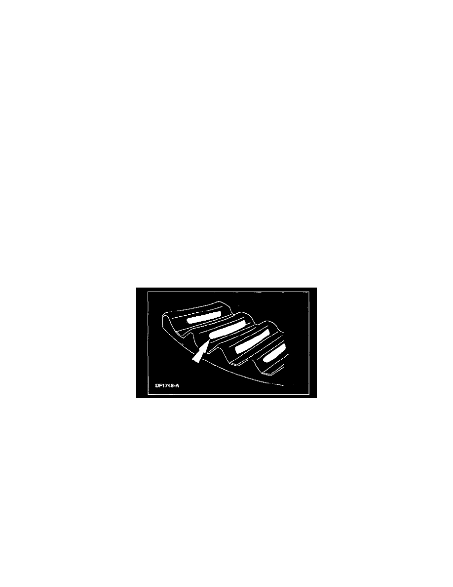
8.
A high, thick contact pattern that is worn more toward the toe.
^
Tooth contact pattern shown on the drive side of the gear teeth.
^
The high contact pattern indicates that the drive pinion is not installed deep enough into the carrier.