
Econoline E350 1 Ton V8-5.4L Prop SOHC VIN Z (1998)
10. Inspect the (A) front and the (B) rear input shaft bushings. If scored or worn, replace the entire pump.
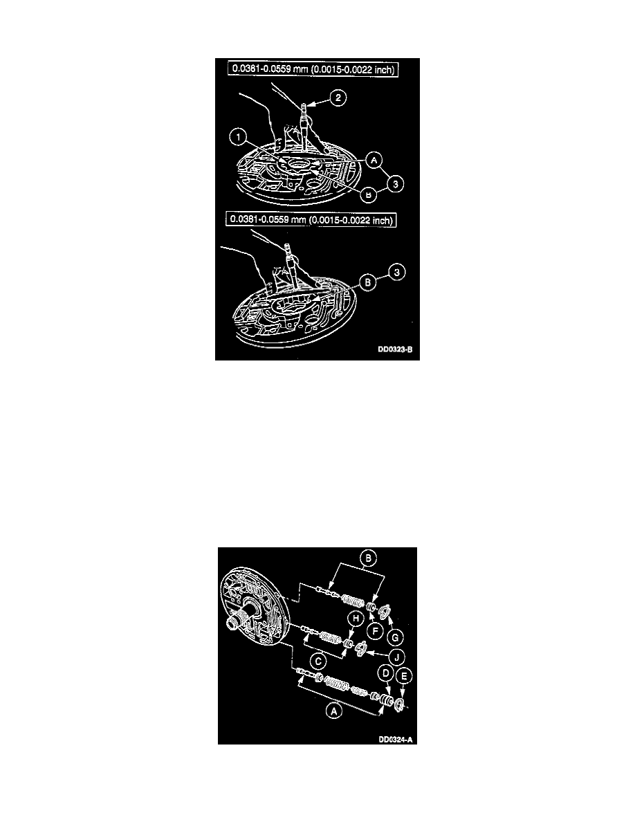
11. Measure and record the depth of the inner, then the outer, pump gerotor gear face-to-pump body machined surface.
1. Place the pump gerotor gear set into the pump gear pocket and center it to the pump bushing diameter.
2. Using a depth micrometer, measure and record the depth of the inner gerotor gear face to the pump body machined surface. Repeat
measurement for a total of three readings in equally spaced locations on the gear face. If the reading is not within specification, replace the
front pump assembly.
3. Remove the (A) inner gear and reinstall the (B) outer gear. Repeat Substep 2 for the outer gerotor gear face.
12. Inspect the following:
-
All valve and plug bores for scoring or damage.
-
All passages for obstructions.
-
Mating surfaces for burrs and scoring,
-
All springs for distortion.
-
When dry, check all valves and plugs for free movement in their respective bores.
ASSEMBLY
1. Install the (A) main regulator valve and sleeve assembly, the (B) converter clutch shift valve assembly, and the (C) converter regulator valve
assembly.
1. Install the (A) main regulator boost valve and sleeve assembly. Then, apply pressure to the (D) main regulator booster sleeve and install the