
Camshaft
- Make
- Ford
- Model
- Edge Factory Service Manual
- Year
- 2007
- Section
- 303-01 Engine — 3.5L › Removal › Camshaft
Camshaft
 |
3-Jaw Puller
303-D121 |
 |
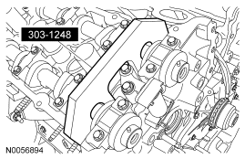
Camshaft Alignment Tool
303-1248 |
 |
Disconnect Tool, Transmission Cooler Tube
307-569 |
 |
Handle
205-153 (T80T-4000-W) |
 |
Powertrain Lift
014-00765 |
 |
Remover, Front Hub
205-D070 (D93P-1175-B) or equivalent |
 |
Remover, Halfshaft (Extension)
205-243 (T89P-3415-A) |
 |
Remover, Halfshaft (Plate)
205-290 (T89P-3415-B) |
 |
Remover, Oil Seal
303-409 (T92C-6700CH) |
 |
Seal Remover
303-1247/1 |
 |
Slide Hammer
100-001 (T50T-100-A) |
 |
Strap Wrench
303-D055 (D85L-6000-A) |
 |
Tie-Rod End Remover
211-105 |
 |
Universal Adapter Brackets
014-0001 Lifting Bracket Set, Engine 303-D095 (D94L-6001-A) or equivalent |
| Item | Specification |
|---|---|
| Motorcraft Metal Surface Prep ZC-31 | — |
| Silicone Gasket Remover ZC-30 | — |
WARNING: Do not smoke or carry lighted tobacco or open flame of any type when working on or near any fuel-related components. Highly flammable mixtures are always present and may be ignited. Failure to follow these instructions may result in personal injury.
CAUTION: During engine repair procedures, cleanliness is extremely important. Any foreign material, including any material created while cleaning gasket surfaces that enters the oil passages, coolant passages or the oil pan, can cause engine failure.
All vehicles
- With the vehicle in NEUTRAL, position it on a hoist. For additional information, refer to Section 100-02.
- Recover the air conditioning system. For additional information, refer to Section 412-00.
- Release the fuel system pressure. For additional information, refer to Section 310-00.
- Drain the engine cooling system. For additional information, refer to Section 303-03.
- Remove the accessory drive belt and the power steering belt. For additional information, refer to Section 303-05.
- Disconnect the power steering cooler hose and drain the power steering fluid into a suitable drain pan.
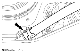
- Remove the degas bottle. For additional information, refer to Section 303-03.
- Remove the engine air cleaner and air cleaner outlet pipe. For additional information, refer to Section 303-12.
- Remove the battery tray. For additional information, refer to Section 414-01.
- Disconnect the battery harness electrical connector.
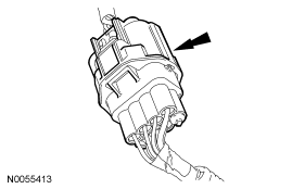
- Remove the nut and disconnect the power feed from the battery terminal.
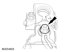
- Remove the bolt and the ground wire.
- Detach the 2 wiring harness retainers from the cowl.
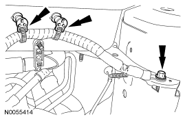
- Disconnect the vacuum hose from the upper intake manifold.
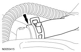
- Disconnect the upper evaporative emissions (EVAP) tube quick connect coupling from the purge valve. For additional information, refer to Section 310-00.
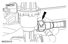
- Disconnect the upper radiator hose, lower radiator hose and 2 heater hoses from the thermostat housing.
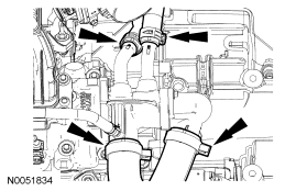
- Detach the wiring harness retainer from the transaxle control cable bracket.
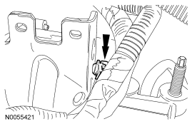
- Disconnect the transaxle control cable from the control lever.
- Detach the control cable from the bracket.
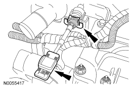
- Disconnect the transaxle control electrical connector.
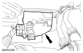
- If equipped, detach the engine block heater harness retainers from the radiator support and the A/C suction tube.
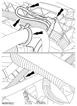
- Remove the nut and disconnect the A/C pressure tube fitting.
- Discard the O-ring seal.
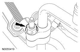
- Remove the safety clip from the A/C fitting.
- Disconnect the A/C suction tube fitting.
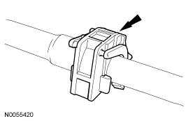
- Disconnect the hose from the power steering reservoir.
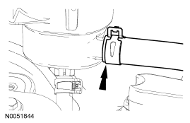
- Disconnect the fuel supply tube. For additional information, refer to Section 310-00.
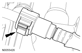
- Disconnect the fuel hose routing clip from the transaxle stud and position the fuel hose aside.
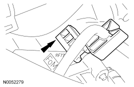
- Disconnect the 2 engine wiring harness electrical connectors.
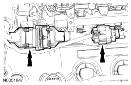
- Detach the electrical connector from the LH valve cover.
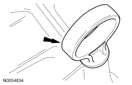
- Remove the oil level indicator.
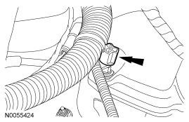
- Detach the wiring harness retainer from the RH valve cover stud bolt.
- Remove the bolt and the ground wire from the engine front cover.
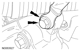
- Remove the nut, the ground wire and the radio interference capacitor wire from the engine front cover stud.
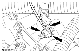
- Loosen the exhaust flexible pipe clamp and disconnect the 2 exhaust hangers.
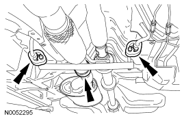
- Remove the 4 nuts and the exhaust flexible pipe and Y-pipe as an assembly.
- Discard the nuts and the gasket.
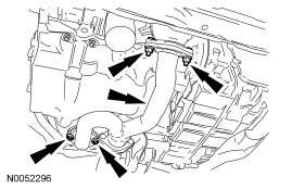
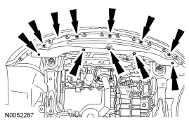
- Remove the 3 pin-type retainers, the 7 screws and the radiator splash shield.
- Remove the LH inner splash shield. For additional information, refer to Section 501-02.
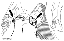
- Remove the 2 secondary latches from the transmission fluid cooler tubes.
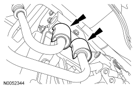
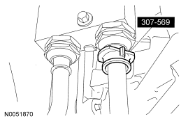
- Using the special tool, disconnect the transaxle cooling tubes.
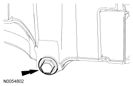
- Remove the drain plug and drain the engine oil.
- Install the drain plug and tighten to 27 Nm (20 lb-ft).
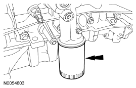
- Remove and discard the engine oil filter.
- Remove the power steering cooler bracket bolt from the RH side of the subframe.
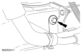
All wheel drive (AWD) vehicles
-
NOTE: Index-mark the driveshaft for installation.
Remove the 4 bolts and support the driveshaft with a length of mechanic's wire.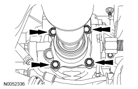
All vehicles
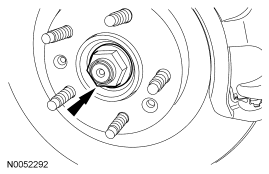
- Remove and discard the RH front halfshaft nut.
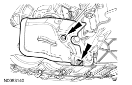
- Remove the 2 nuts and the roll restrictor heat shield.
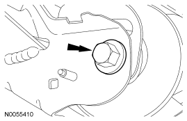
- Remove the engine roll restrictor-to-subframe through bolt.
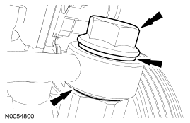
- Remove and discard the power steering pressure (PSP) tube-to-pump banjo bolt and the 2 seals.
-
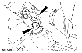
CAUTION: Do not allow the intermediate shaft to rotate while it is disconnected from the gear or damage to the clockspring can occur. If there is evidence that the intermediate shaft has rotated, the clockspring must be removed and recentered. For additional information, refer to Section 501-20B.
Remove and discard the steering intermediate shaft bolt.- Separate the steering intermediate shaft from the steering gear.
-
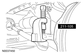
NOTE: RH shown, LH similar.
Remove and discard the cotter pins and tie-rod end nuts.- Using the special tool, separate the tie-rod ends from the wheel knuckles.
-
NOTE: RH shown, LH similar.
Remove the 2 stabilizer link-to-lower control arm nuts and separate the stabilizer bar links from the lower control arms.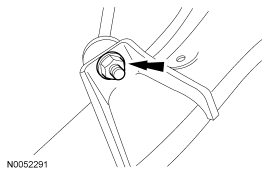
-
NOTE: RH shown, LH similar.
Remove the lower control arm-to-knuckle pinch bolts and separate the lower control arms from the knuckles.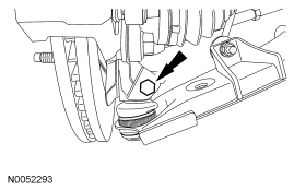
- Remove the 3 RH subframe-to-lower bumper nuts.
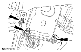
- Remove the 3 LH subframe-to-lower bumper nuts and separate the lower bumper from the subframe.
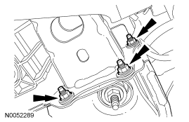
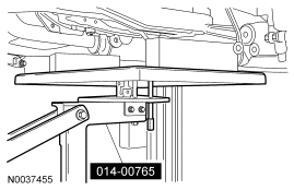
- Position the special tool under the subframe assembly.
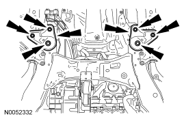
- Remove the 2 nuts, 4 bolts and the subframe support brackets.
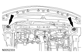
- Remove the 2 front subframe nuts.
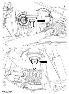
- Remove the 2 middle subframe nuts.
- Using the special tool, lower the subframe assembly from the vehicle.
- If equipped, disconnect the oil cooler coolant hoses.
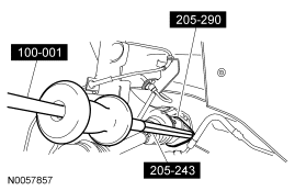
- Using the special tools, separate the LH halfshaft from the transaxle and support the halfshaft with a length of mechanic's wire.
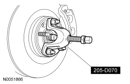
- Using the special tool, separate the RH halfshaft from the hub.
Front wheel drive (FWD) vehicles
- Remove the 2 RH catalytic converter support bracket bolts.
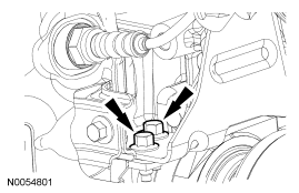
- Remove the bolt, the nut and the RH catalytic converter support bracket.
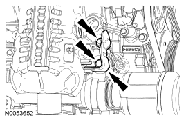
- Remove the 2 stud bolts and the RH halfshaft/intermediate shaft assembly.
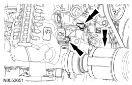
AWD vehicles
- Remove the 2 RH halfshaft bearing support bracket bolts and the RH halfshaft/intermediate shaft assembly.
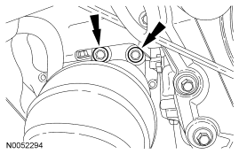
All vehicles
-
NOTE: Position a block of wood under the transaxle.
Install the special tools.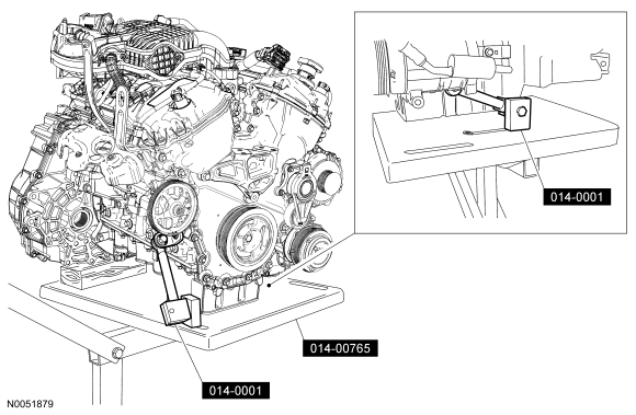
- Remove the transaxle support insulator through bolt and nut.
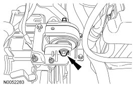
- Remove the 3 nuts, the bolt and the transaxle support insulator bracket.
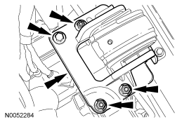
- Remove the nut, bolt and engine mount brace.
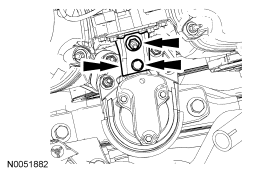
- Remove the 4 engine mount nuts.
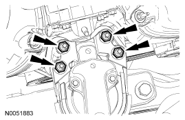
- Remove the 3 bolts and the engine mount.
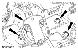
- Lower the engine and transaxle assembly from the vehicle.
- If equipped, detach the engine block heater wiring harness retainers and position the harness aside.
- Disconnect the positive crankcase ventilation (PCV) fitting electrical connector.
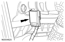
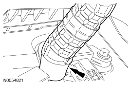
- Disconnect the PCV hose from the PCV valve.
- Disconnect the throttle body electrical connector.
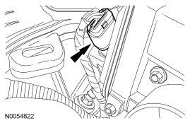
- Detach the wiring harness retainers from the upper intake manifold.
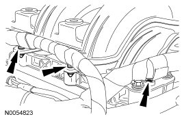
- Remove the upper intake manifold support bracket bolt.
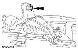
- Remove the upper intake manifold support bracket bolt.
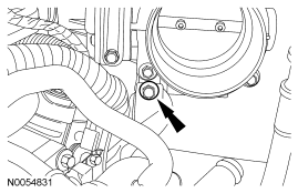
- Remove the 6 bolts and the upper intake manifold.
- Discard the gaskets.
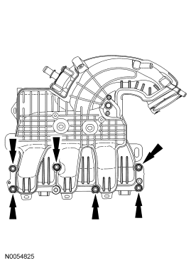
- Disconnect the RH catalyst monitor electrical connector.
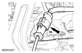
- Disconnect the PSP switch electrical connector.
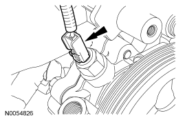
- Disconnect the RH variable camshaft timing (VCT) solenoid electrical connector.
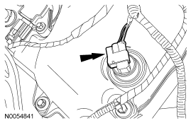
- Disconnect the 3 RH coil-on-plug electrical connectors.
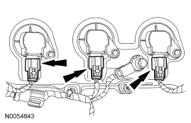
- Disconnect the heated PCV valve electrical connector.
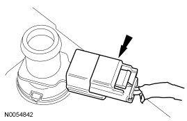
- Detach all of the wiring harness retainers from the RH valve cover and stud bolts.
- Disconnect the LH VCT solenoid electrical connector.
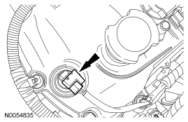
- Disconnect the 3 LH coil-on-plug electrical connectors.
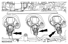
- Detach all of the wiring harness retainers from the LH valve cover and stud bolts.
-
NOTE: LH shown, RH similar.
Remove the 6 bolts and the 6 coil-on-plugs.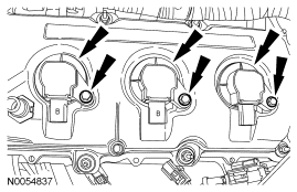
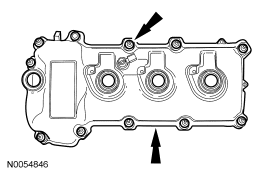
- Remove the 11 stud bolts and the LH valve cover.
- Discard the gasket.
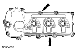
- Remove the bolt, the 10 stud bolts and the RH valve cover.
- Discard the gasket.
-
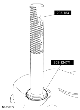
NOTE: VCT solenoid seal removal shown, spark plug tube seal removal similar.
Inspect the VCT solenoid seals and the spark plug tube seals. Install new seals if damaged.- Using the special tools, remove the seal(s).
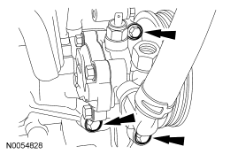
- Remove the 3 bolts and the power steering pump.
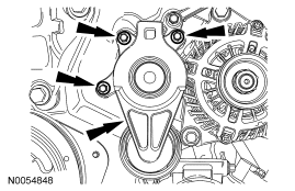
- Remove the 3 bolts and the accessory drive belt tensioner.
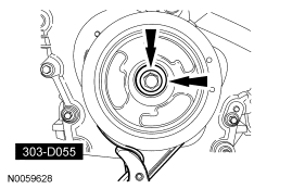
- Using the special tool, remove the crankshaft bolt and washer.
- Discard the bolt.
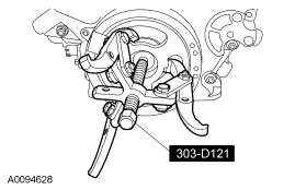
- Using the special tool, remove the crankshaft pulley.
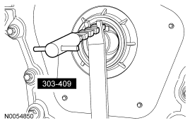
- Using the special tool, remove and discard the crankshaft front seal.
- Remove the 2 bolts and the engine mount bracket.
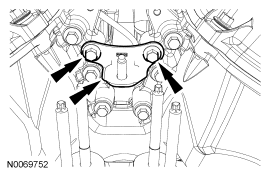
- Remove the 2 engine mount studs.
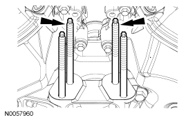
- Remove the 3 bolts and the engine mount bracket.
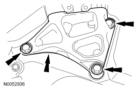
- Remove the 22 engine front cover bolts.
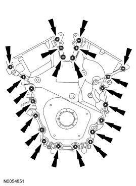
- Install 6 of the engine front cover bolts (finger tight) into the 6 threaded holes in the engine front cover.
- Tighten the bolts one turn at a time in a criss-cross pattern until the engine front cover-to-cylinder block seal is released.
- Remove the engine front cover.
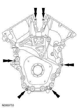
-
CAUTION: Only use a 3M Roloc® Bristle Disk, (2 inch, white, part number 07528) to clean the engine front cover. Do not use metal scrapers, wire brushes or any other power abrasive disk to clean the engine front cover. These tools cause scratches and gouges that make leak paths.
Clean the engine front cover using a 3M Roloc® Bristle Disk, (2 inch, white, part number 07528) in a suitable tool turning at the recommended speed of 15,000 rpm.- Thoroughly wash the engine front cover to remove any foreign material, including any abrasive particles created during the cleaning process.
-
CAUTION: Place clean, lint free shop towels over exposed engine cavities. Carefully remove the towels so foreign material is not dropped into the engine. Any foreign material (including any material created while cleaning gasket surfaces) that enters the oil passages or the oil pan, can cause engine failure.
CAUTION: Do not use metal scrapers, wire brushes, power abrasive discs or other abrasive means to clean the sealing surfaces. These tools cause scratches and gouges that make leak paths. Use a plastic scraping tool to remove all traces of sealant.
CAUTION: Observe all warnings or cautions and follow all application directions contained on the packaging of the silicone gasket remover and the metal surface prep.
Clean the sealing surfaces of the cylinder block.- Remove any large deposits of silicone or gasket material with a plastic scraper.
- Apply silicone gasket remover, following package directions, and allow to set for several minutes.
- Remove the silicone gasket remover with a plastic scraper. A second application of silicone gasket remover may be required if residual traces of silicone or gasket material remain.
- Apply metal surface prep, following package directions, to remove any remaining traces of oil or coolant and to prepare the surfaces to bond. Do not attempt to make the metal shiny. Some staining of the metal surfaces is normal.
- Make sure the 2 locating dowel pins are seated correctly in the cylinder block.
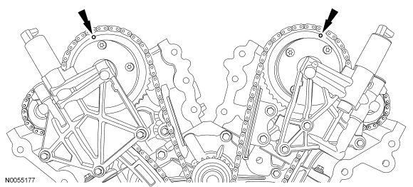
- Rotate the crankshaft clockwise and align the timing marks on the variable camshaft timing (VCT) assemblies as shown.
-
NOTE: The special tool will hold the camshafts in the top dead center position.
Install the special tool onto the flats of the LH camshafts.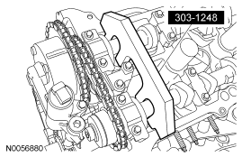
-
NOTE: The special tool will hold the camshafts in the top dead center position.
Install the special tool onto the flats of the RH camshafts.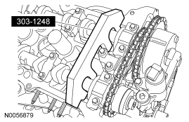
- Remove the 3 bolts and the RH VCT housing.
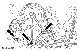
- Remove the 3 bolts and the LH VCT housing.
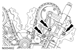
- Remove and discard the VCT housing seals.
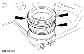
- Remove the 2 bolts and the primary timing chain tensioner.
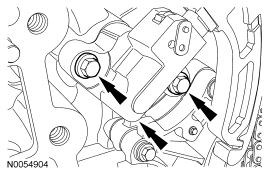
- Remove the primary timing chain tensioner arm.
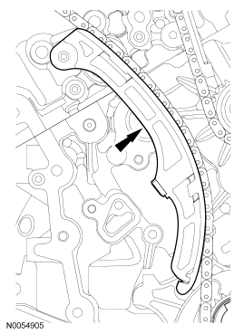
- Remove the 2 bolts and the lower LH primary timing chain guide.
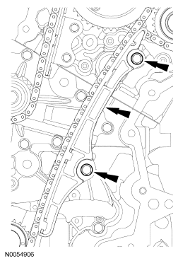
- Remove the primary timing chain.
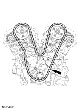
LH camshafts
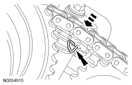
- Compress the LH secondary timing chain tensioner and install a suitable lockpin to retain the tensioner in the collapsed position.
-
NOTE: The VCT bolt and the exhaust camshaft bolt must be discarded and new ones installed. However, the exhaust camshaft washer is reusable.
Remove and discard the LH VCT assembly bolt and the LH exhaust camshaft sprocket bolt.- Remove the LH VCT assembly, secondary timing chain and the LH exhaust camshaft sprocket as an assembly.
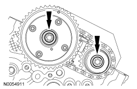
-
NOTE: When the special tool is removed, valve spring pressure will rotate the LH camshafts approximately 3 degrees to a neutral position.
Remove the special tool from the LH camshafts.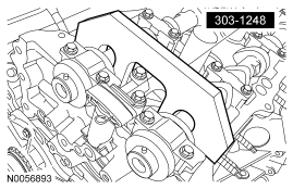
-
CAUTION: The camshafts must remain in the neutral position during removal.
Verify the LH camshafts are in the neutral position.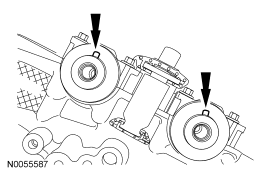
-
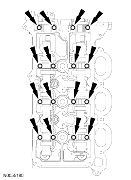
CAUTION: Cylinder head camshaft bearing caps are numbered to verify that they are assembled in their original positions.
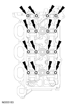
Remove the bolts and the LH camshaft bearing caps.- Remove the LH camshafts.
RH camshafts
- Compress the RH secondary timing chain tensioner and install a suitable lockpin to retain the tensioner in the collapsed position.
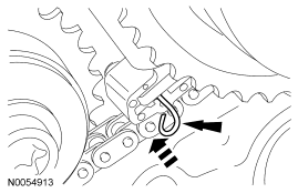
-
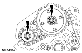
NOTE: The VCT bolt and the exhaust camshaft bolt must be discarded and new ones installed. However, the exhaust camshaft washer is reusable.
Remove and discard the RH VCT assembly bolt and the RH exhaust camshaft sprocket bolt.- Remove the RH VCT assembly, secondary timing chain and the RH exhaust camshaft sprocket as an assembly.
- Remove the special tool from the RH camshafts.
-
CAUTION: The camshafts must remain in the neutral position during removal.
Rotate the RH camshafts counterclockwise to the neutral position.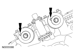
-
CAUTION: Cylinder head camshaft bearing caps are numbered to verify that they are assembled in their original positions.
Remove the bolts and the RH camshaft bearing caps.- Remove the RH camshafts.
Parts & tools for this job For 2007 Ford Edge
- PARTEngine gasket setSearch: Ford Edge 2007 engine gasket set
- TOOLTorque wrenchSearch: 3/8 inch torque wrench
- TOOLFeeler gauge setSearch: feeler gauge set
Links open Amazon search results in a new tab. As an Amazon Associate I earn from qualifying purchases.