
Edge AWD V6-3.5L (2009)
Principles of Operation
The Driver Seat Module (DSM) communicates on the Medium Speed Controller Area Network (MS-CAN). The vehicle is not equipped with a DSM if
the vehicle does not have a driver memory seat. If the vehicle is equipped with a DSM, it uses the MS-CAN communication network to permit
inter-module and scan tool communications. The vehicle may have both memory driver seat and memory exterior mirrors, or only memory driver seat, or
neither memory driver seat or memory exterior mirrors.
The DSM controls the memory driver seat and the memory exterior mirrors. The memory feature allows the driver to program personalized seat/mirror
positions. Once the driver stores a memory position, the setting can be recalled by pressing the corresponding memory switch or by using a programmed
Remote Keyless Entry (RKE) Integrated Keyhead Transmitter (IKT). Refer to Seats.
Special Tools Used With Diagnostics
Driver Seat Module (DSM)
Inspection and Verification
Smart Junction Box (SJB)
Inspection and Verification
1. Verify the customer concern.
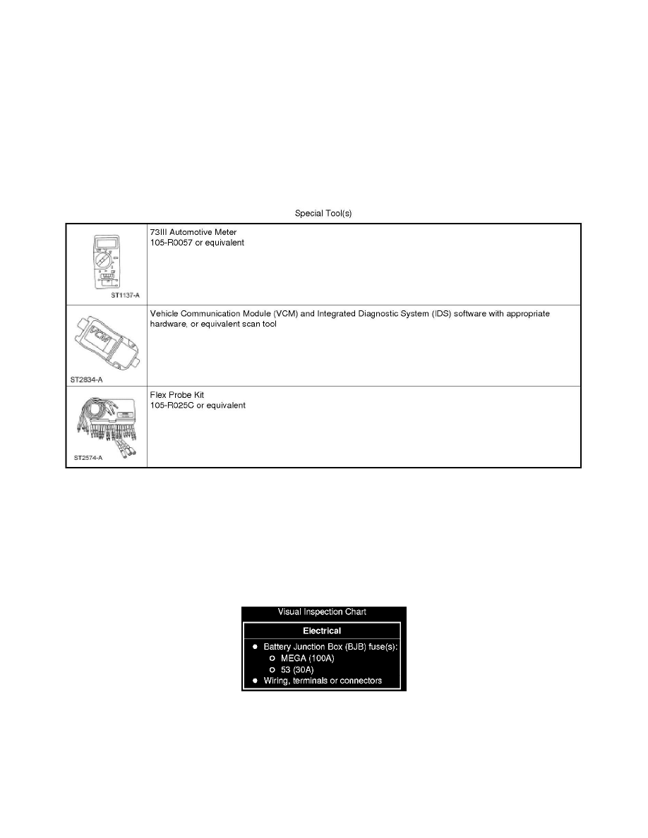
2. Visually inspect for obvious signs of electrical damage.
Visual Inspection Chart
3. If an obvious cause for an observed or reported concern is found, correct the cause (if possible) before proceeding to the next step.
4. NOTE: Make sure to use the latest scan tool software release.
If the cause is not visually evident, connect the scan tool to the Data Link Connector (DLC).
5. NOTE: The Vehicle Communication Module (VCM) LED prove-out confirms power and ground from the DLC are provided to the VCM.