
Cylinder Head
- Make
- Ford
- Model
- Expedition Factory Service Manual
- Year
- 2007
- Section
- 303-01 Engine › Removal › Cylinder Head
Cylinder Head
 |
Locking Tool, Camshaft Phaser Sprocket
303-1046 |
 |
Remover, Crankshaft Front Seal
303-107 (T74P-6700-A) |
 |
Remover, Crankshaft Vibration Damper
303-009 (T58P-6316-D) |
 |
Remover/Installer, Cylinder Head
303-572 (T97T-6000-A) |
 |
Modular Engine Lift Bracket
303-F047 (014-00073) or equivalent |
 |
Compressor, Valve Spring
303-1039 |
| Item | Specification |
|---|---|
| Motorcraft Metal Surface Prep ZC-31 | — |
| Silicone Gasket Remover ZC-30 | — |
All cylinder heads
- Remove the engine. For additional information, refer to Engine in the Removal portion of this section.
- Remove the bolts and the flexplate.
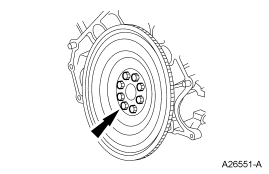
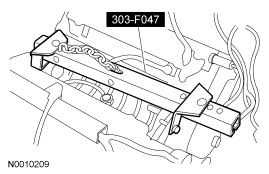
- Install the engine onto a suitable engine stand.
- Remove the special tool.
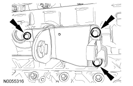
- Remove the 3 bolts and the RH engine support insulator bracket.
-
NOTE: LH shown, RH similar.
Remove the cylinder block drain plugs and drain the coolant into a suitable container.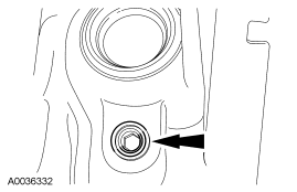
-
NOTE: LH shown, RH similar.
Install the cylinder block drain plugs.- Tighten to 24 Nm (18 lb-ft).
-
NOTE: RH shown, LH similar.
Disconnect the RH and LH camshaft position (CMP) sensor electrical connectors.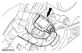
- Remove the nut and the RH radio ignition interference capacitor.
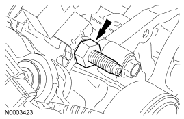
-
NOTE: RH shown, LH similar.
Disconnect the RH and LH variable camshaft timing (VCT) solenoid electrical connector.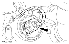
- Disconnect the 2 engine wiring harness retainers from the RH valve cover studs.
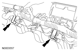
- Disconnect the electrical connector retainer from the coolant tube.
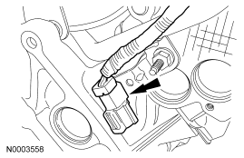
- Disconnect the cylinder head temperature (CHT) sensor electrical connector.
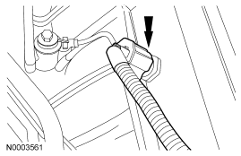
- Disconnect the 2 engine wiring harness retainers from the LH valve cover studs.
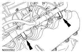
- Remove the nut and the LH radio ignition interference capacitor.
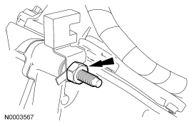
-
NOTE: LH shown, RH similar.
Remove the 8 bolts and the 8 ignition coils.- Remove the ignition coil using a twisting motion while pulling up on the ignition coil.
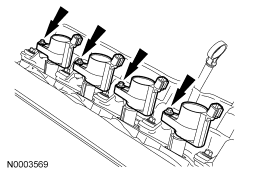
- Remove the engine wiring harness from the engine assembly.
- Remove the bolt and the oil level indicator tube.
- Discard the O-ring seal.
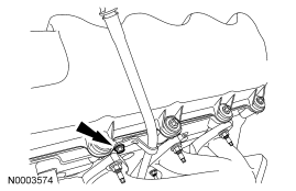
- Remove the bolt and the RH CMP sensor.
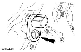
- Remove the bolt and the LH CMP sensor.
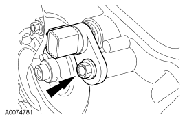
- Remove the bolt and the CKP sensor.
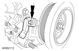
-
CAUTION: Do not use metal scrapers, wire brushes, power abrasive discs or other abrasive means to clean the sealing surfaces. These tools cause scratches and gouges which make leak paths. Use a plastic scraping tool to remove all traces of old sealant.
CAUTION: When removing the valve cover, make sure to avoid damaging the variable camshaft timing (VCT) solenoid.
NOTE: The fasteners are part of the valve cover and should not be removed.
NOTE: LH shown, RH similar.
Loosen the fasteners and remove the valve covers.- Clean the valve cover mating surface of the cylinder head with silicone gasket remover and metal surface prep. Follow the directions on the packaging.
- Inspect the valve cover gasket. If the gasket is damaged, remove and discard the gasket. Clean the valve cover gasket groove with soap and water or a suitable solvent.
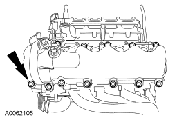
- Remove the bolts, the coolant pump pulley and the 3 accessory drive belt idler pulleys.
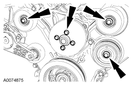
- Remove and discard the crankshaft pulley bolt. Using the special tool, remove the crankshaft pulley.
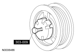
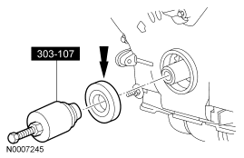
- Using the special tool, remove and discard the crankshaft front seal.
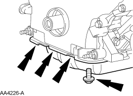
- Remove the front 4 oil pan bolts.
-
NOTE: Correct fastener location is essential for assembly procedure. Record fastener location.
Remove the fasteners.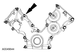
- Remove the engine front cover from the cylinder block.
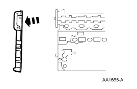
- Remove the crankshaft sensor ring from the crankshaft.
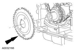
- Position the crankshaft keyway at the 12 o'clock position.
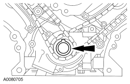
-
NOTE: If the camshaft lobes are not exactly positioned as shown, the crankshaft will require one full additional rotation to 12 o'clock.
The No. 1 cylinder camshaft exhaust lobe must be coming up on the exhaust stroke. Verify by noting the position of the 2 intake camshaft lobes and the exhaust lobe on the No. 1 cylinder.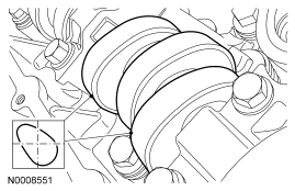
-
CAUTION: If the components are to be reinstalled, they must be installed in the same positions. Mark the components for installation into the original locations. Failure to follow these instructions may result in engine damage.
Remove only the 3 camshaft roller followers shown in the illustration from the RH cylinder head.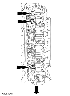
-
NOTE: Do not allow the valve keepers to fall off the valve or the valve may drop into the cylinder.
NOTE: It may be necessary to push the valve down while compressing the spring.
Using the special tool, remove the 3 camshaft roller followers designated in the previous step from the RH cylinder head.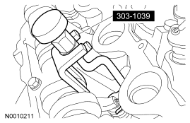
-
CAUTION: If the components are to be reinstalled, they must be installed in the same positions. Mark the components for installation into the original locations. Failure to follow these instructions may result in engine damage.
Remove only the 3 camshaft roller followers shown in the illustration from the LH cylinder head.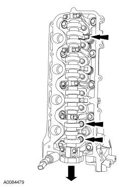
-
NOTE: Do not allow the valve keepers to fall off the valve or the valve may drop into the cylinder.
NOTE: It may be necessary to push the valve down while compressing the spring.
Using the special tool, remove the 3 camshaft roller followers designated in the previous step from the LH cylinder head.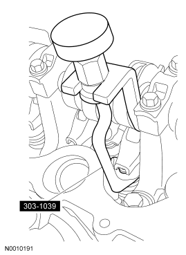
-
CAUTION: The crankshaft cannot be moved past the 6 o'clock position once set or engine damage may occur.
Rotate the crankshaft clockwise and position the crankshaft keyway at the 6 o'clock position.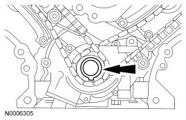
-
CAUTION: If one or both of the tensioner mounting bolts are loosened or removed, the tensioner-sealing bead must be inspected for seal integrity. If cracks, tears, separation from the tensioner body or permanent compression of the seal bead is observed, install a new tensioner. Failure to follow these instructions may result in engine damage.
Remove the bolts, the LH timing chain tensioner and tensioner arm.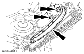
-
CAUTION: If one or both of the tensioner mounting bolts are loosened or removed, the tensioner-sealing bead must be inspected for seal integrity. If cracks, tears, separation from the tensioner body or permanent compression of the seal bead is observed, install a new tensioner. Failure to follow these instructions may result in engine damage.
Remove the bolts, the RH timing chain tensioner and tensioner arm.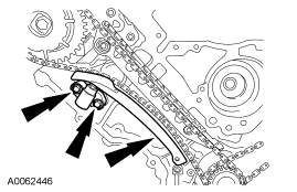
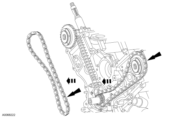
- Remove the RH and LH timing chains and the crankshaft sprocket.
- Remove the RH timing chain from the camshaft sprocket.
- Remove the RH timing chain from the crankshaft sprocket.
- Remove the LH timing chain from the camshaft sprocket.
- Remove the LH timing chain and crankshaft sprocket.
-
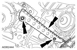
NOTE: RH shown, LH similar.
Remove the LH and RH timing chain guides.- Remove the bolts.
- Remove both timing chain guides.
-
CAUTION: Damage to the variable camshaft timing (VCT) phaser sprocket assembly will occur if mishandled or used as a lifting or leveraging device.
CAUTION: Only use hand tools to remove the variable camshaft timing (VCT) phaser sprocket assembly or damage may occur to the camshaft or VCT phaser sprocket.
Using the special tool, remove the bolt and the RH VCT phaser sprocket assembly.- Discard the camshaft phaser sprocket bolt.
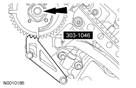
-
CAUTION: Damage to the variable camshaft timing (VCT) phaser sprocket assembly will occur if mishandled or used as a lifting or leveraging device.
CAUTION: Only use hand tools to remove the variable camshaft timing (VCT) phaser sprocket assembly or damage may occur to the camshaft or VCT phaser sprocket.
Using the special tool, remove the bolt and the LH VCT phaser sprocket assembly.- Discard the camshaft phaser sprocket bolt.
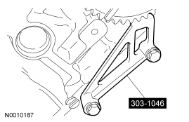
-
CAUTION: Remove the front thrust camshaft bearing cap straight upward from the bearing towers or the bearing cap may be damaged from side loading.
Remove the 2 bolts and the RH camshaft front bearing cap.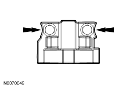
-
CAUTION: The camshaft bearing caps must be installed in their original locations. Record camshaft bearing cap locations. Failure to follow these instructions may result in engine damage.
Remove the remaining bolts in the sequence shown and remove the remaining RH camshaft bearing caps.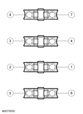
- Clean and inspect the RH camshaft bearing caps.
- The camshaft front thrust bearing cap contains an oil metering groove. Make sure the groove is free of foreign material.
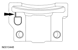
- Remove the RH camshaft.
-
CAUTION: Remove the front thrust camshaft bearing cap straight upward from the bearing towers or the bearing cap may be damaged from side loading.
Remove the 2 bolts and the LH camshaft front bearing cap. -
CAUTION: The camshaft bearing caps must be installed in their original locations. Record camshaft bearing cap locations. Failure to follow these instructions may result in engine damage.
Remove the remaining bolts in the sequence shown and remove the remaining LH camshaft bearing caps. - Clean and inspect the LH camshaft bearing caps.
- The camshaft front thrust bearing cap contains an oil metering groove. Make sure the groove is free of foreign material.
- Remove the LH camshaft.
-
CAUTION: If the components are to be reinstalled, they must be installed in the same positions. Mark the components for installation into the original locations. Failure to follow these instructions may result in engine damage.
Remove all of the remaining camshaft roller followers from the cylinder heads.
LH cylinder head
-
CAUTION: If the components are to be reinstalled, they must be installed in the same positions. Mark the components for installation into the original locations. Failure to follow these instructions may result in engine damage.
Remove the hydraulic lash adjusters from the LH cylinder head. - Install the special tool onto the LH cylinder head.
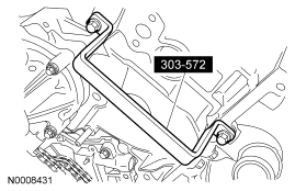
- Remove the 3 bolts and the exhaust manifold heat shield.
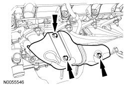
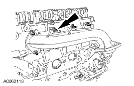
- Remove the 8 nuts, the 8 studs and the LH exhaust manifold.
- Discard the gaskets, nuts and studs.
- Inspect the exhaust manifold. For additional information, refer to Section 303-00.
RH cylinder head
-
CAUTION: If the components are to be reinstalled, they must be installed in the same positions. Mark the components for installation into the original locations. Failure to follow these instructions may result in engine damage.
Remove the hydraulic lash adjusters from the RH cylinder heads. - Install the special tool onto the RH cylinder head.
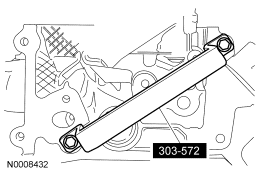
- Remove the 8 nuts, the 8 studs and the RH exhaust manifold.
- Discard the gasket, nuts and studs.
- Inspect the exhaust manifold. For additional information, refer to Section 303-00.
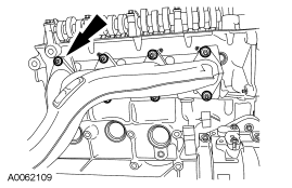
- Remove the stud bolt and the coolant tube.
- Discard the O-ring seals.
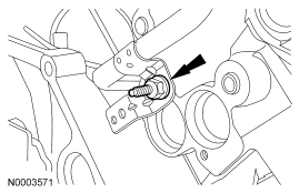
All cylinder heads
-
CAUTION: The cylinder head must be cool before removing it from the engine. Cylinder head warpage can result if a warm or hot cylinder head is removed.
CAUTION: Place clean shop towels over exposed engine cavities. Carefully remove the towels so foreign material is not dropped into the engine.
CAUTION: The cylinder head bolts must be discarded and new bolts must be installed. They are a tighten-to-yield design and cannot be reused.
CAUTION: Do not use metal scrapers, wire brushes, power abrasive discs or other abrasive means to clean the sealing surfaces. These tools cause scratches and gouges that make leak paths. Use a plastic scraping tool to remove all traces of the head gasket.
CAUTION: Aluminum surfaces are soft and can be scratched easily. Never place the cylinder head gasket surface, unprotected, on a bench surface.
NOTE: RH shown, LH similar.
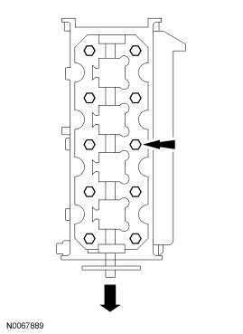
Remove the bolts and the cylinder head.- Discard the cylinder head gasket.
- Discard the cylinder head bolts.
-
CAUTION: Do not use metal scrapers, wire brushes, power abrasive discs or other abrasive means to clean the sealing surfaces. These tools cause scratches and gouges that make leak paths. Use a plastic scraping tool to remove all traces of the head gasket.
CAUTION: Observe all warnings or cautions and follow all application directions contained on the packaging of the silicone gasket remover and the metal surface prep. Failure to follow these instructions may result in engine damage.
NOTE: If there is no residual gasket material present, metal surface prep can be used to clean and prepare the surfaces.
Clean the cylinder head-to-cylinder block mating surfaces of both the cylinder head and the cylinder block in the following sequence.- Remove any large deposits of silicone or gasket material with a plastic scraper.
- Apply silicone gasket remover, following package directions, and allow to set for several minutes.
- Remove the silicone gasket remover with a plastic scraper. A second application of silicone gasket remover may be required if residual traces of silicone or gasket material remain.
- Apply metal surface prep, following package directions, to remove any remaining traces of oil or coolant, and to prepare the surfaces to bond with the new gasket. Do not attempt to make the metal shiny. Some staining of the metal surfaces is normal.
-
NOTE: Make sure all cylinder head surfaces are clear of any gasket material, RTV, oil and coolant. The cylinder head surface must be clean and dry before running a flatness check.
NOTE: Use a straightedge that is calibrated by the manufacturer to be flat within 0.005 mm (0.0002 in) per running foot length. For example, if the straightedge is 61 cm (24 in) long, the machined edge must be flat within 0.010 mm (0.0004 in) from end to end.
NOTE: LH shown, RH similar.
Support the cylinder head on a bench with the head gasket side up. Inspect all areas of the deck face with a straightedge, paying particular attention to the oil pressure feed area. The cylinder head must not have depressions deeper than 0.0254 mm (0.001 in) across a 38.1 mm (1.5 in) square area, or scratches longer than 0.0254 mm (0.001 in).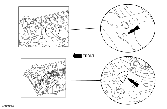
Parts & tools for this job For 2007 Ford Expedition
- PARTEngine gasket setSearch: Ford Expedition 2007 engine gasket set
- TOOLTorque wrenchSearch: 3/8 inch torque wrench
- TOOLFeeler gauge setSearch: feeler gauge set
Links open Amazon search results in a new tab. As an Amazon Associate I earn from qualifying purchases.