
Expedition 2WD V8-5.4L (2009)
Seat Heater Control Module: Service and Repair
Dual Climate Controlled Seat Module (DCSM)
Dual Climate Controlled Seat Module (DCSM)
Removal and Installation
WARNING: Never probe the electrical connectors on safety belt buckle/retractor pretensioners or adaptive load limiting retractors. Failure to
follow this instruction may result in the accidental deployment of the safety belt pretensioners or adaptive load limiting retractors, which
increases the risk of serious personal injury or death.
WARNING: Never probe the electrical connectors on air bag, Safety Canopy(R) or side air curtain modules. Failure to follow this instruction
may result in the accidental deployment of these modules, which increases the risk of serious personal injury or death.
NOTE: The air bag warning indicator illuminates when the correct Restraints Control Module (RCM) fuse is removed and the ignition is ON.
NOTE: The Supplemental Restraint System (SRS) must be fully operational and free of faults before releasing the vehicle to the customer.
NOTE: For component identification and locations, refer to Seat - Exploded View, Front See: Seats/Service and Repair/Front Seats/Seat - Exploded
View, Front.
1. When installing a new Dual Climate Controlled Seat Module (DCSM), carry out the appropriate steps in the Programmable Module Installation
(PMI) procedure. See: Powertrain Management/Computers and Control Systems/Information Bus/Testing and Inspection/Programming and
Relearning
2. NOTICE: Do not pull from the inboard side of the front seat cushion panel shield to avoid damaging it.
Position the front passenger seat fully upward and remove the front seat cushion panel shield.
-
Release the upper retaining clips working from the outboard side and then release the lower retaining clips.
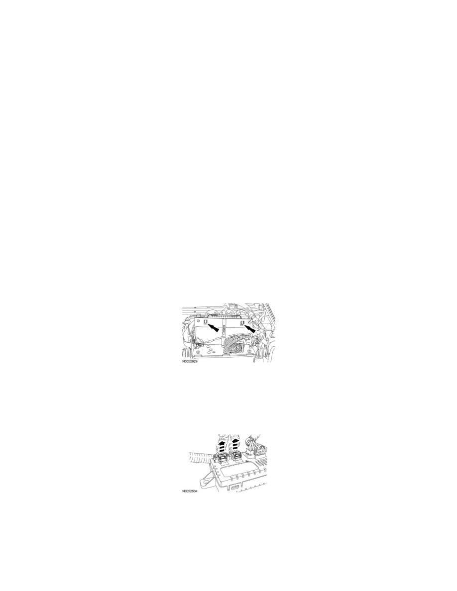
3. Release the 2 tabs and slide out the DCSM.
4. Remove the DCSM.
-
Cut and remove the wiring harness tie strap.
-
Release the 2 locking wedges.
-
Disconnect the 3 electrical connectors.
5. To install, reverse the removal procedure.
6. If a new DCSM has been installed, carry out the appropriate steps in the Programmable Module Installation (PMI) procedure. See: Powertrain
Management/Computers and Control Systems/Information Bus/Testing and Inspection/Programming and Relearning