
Expedition 2WD V8-5.4L (2009)
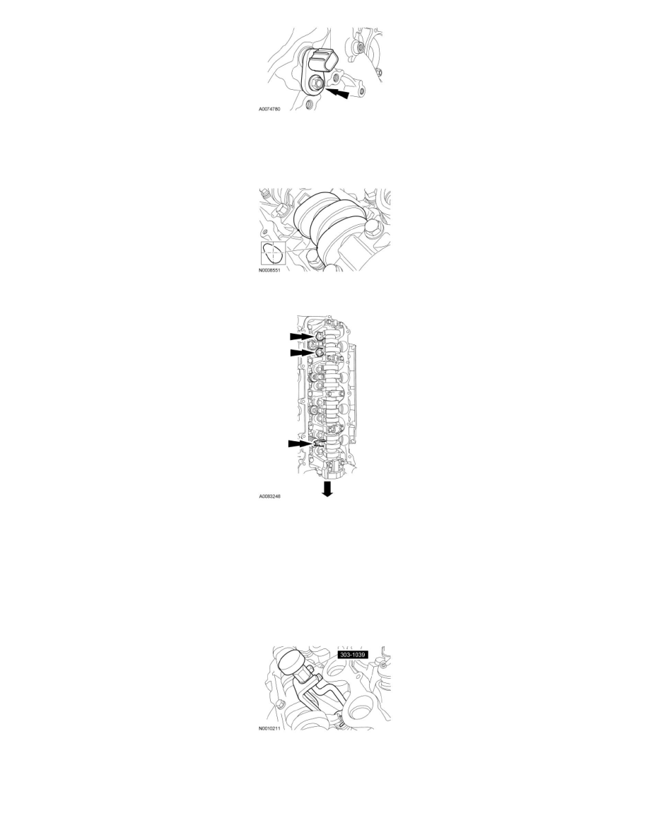
6. NOTE: If the camshaft lobes are not exactly positioned as shown, the crankshaft will require one full additional rotation to 12 o'clock.
The No. 1 cylinder camshaft exhaust lobe must be coming up on the exhaust stroke. Verify by noting the position of the 2 intake camshaft lobes
and the exhaust lobe on the No. 1 cylinder.
7. Remove only the 3 camshaft roller followers shown in the illustration.
8. NOTICE: The camshaft roller followers must be installed in their original locations. Record camshaft roller follower locations. Failure to
follow these instructions may result in engine damage.
NOTE: Do not allow the valve keepers to fall off of the valve or the valve may drop into the cylinder. If a valve drops into the cylinder, the
cylinder head must be removed. For additional information, refer to Cylinder Head See: Cylinder Head Assembly/Service and Repair/Removal
and Replacement/Cylinder Head - Removal.
NOTE: It may be necessary to push the valve down while compressing the spring.
Using the Valve Spring Compressor, remove only the 3 designated camshaft roller followers from the previous step.
9. NOTICE: The crankshaft cannot be moved past the 6 o'clock position once set or engine damage may occur.
Rotate the crankshaft clockwise, as viewed from the front, positioning the crankshaft damper spoke at the 6 o'clock position and the timing mark
indentation at the 7 o'clock position.