
Expedition 2WD V8-5.4L (2009)
Pinpoint Test L: The Audio Digital Signal Processing (DSP) Module Does Not Respond To The Scan Tool
Refer to Wiring Diagram Set 14, Module Communications Network for schematic and connector information. See: Diagrams/Electrical
Diagrams/Diagrams By Number
Refer to Wiring Diagram Set 130, Audio System/Navigation for schematic and connector information. See: Diagrams/Electrical Diagrams/Diagrams By
Number
Normal Operation
The audio Digital Signal Processing (DSP) module communicates with the scan tool through the Medium Speed Controller Area Network (MS-CAN).
Circuits VDB06 (GY/OG) (MS-CAN +) and VDB07 (VT/OG) (MS-CAN -) provide the network connection to the audio DSP module. Voltage for the
audio DSP module is provided by circuits SBP38 (BN/RD) and SBP40 (VT/RD). Three circuits GD114 (BK/BU) provide ground.
This pinpoint test is intended to diagnose the following:
-
Fuses
-
Wiring, terminals or connectors
-
Audio DSP module
PINPOINT TEST L: THE AUDIO DSP MODULE DOES NOT RESPOND TO THE SCAN TOOL
NOTICE: Use the correct probe adapter(s) when making measurements. Failure to use the correct probe adapter(s) may damage the
connector.
NOTE: Failure to disconnect the battery when instructed will result in false resistance readings. Refer to Battery.
-------------------------------------------------
L1 CHECK THE AUDIO DSP MODULE VOLTAGE SUPPLY CIRCUITS FOR AN OPEN
-
Ignition OFF.
-
Disconnect: Audio DSP Module C2364a.
-
Ignition ON.
-
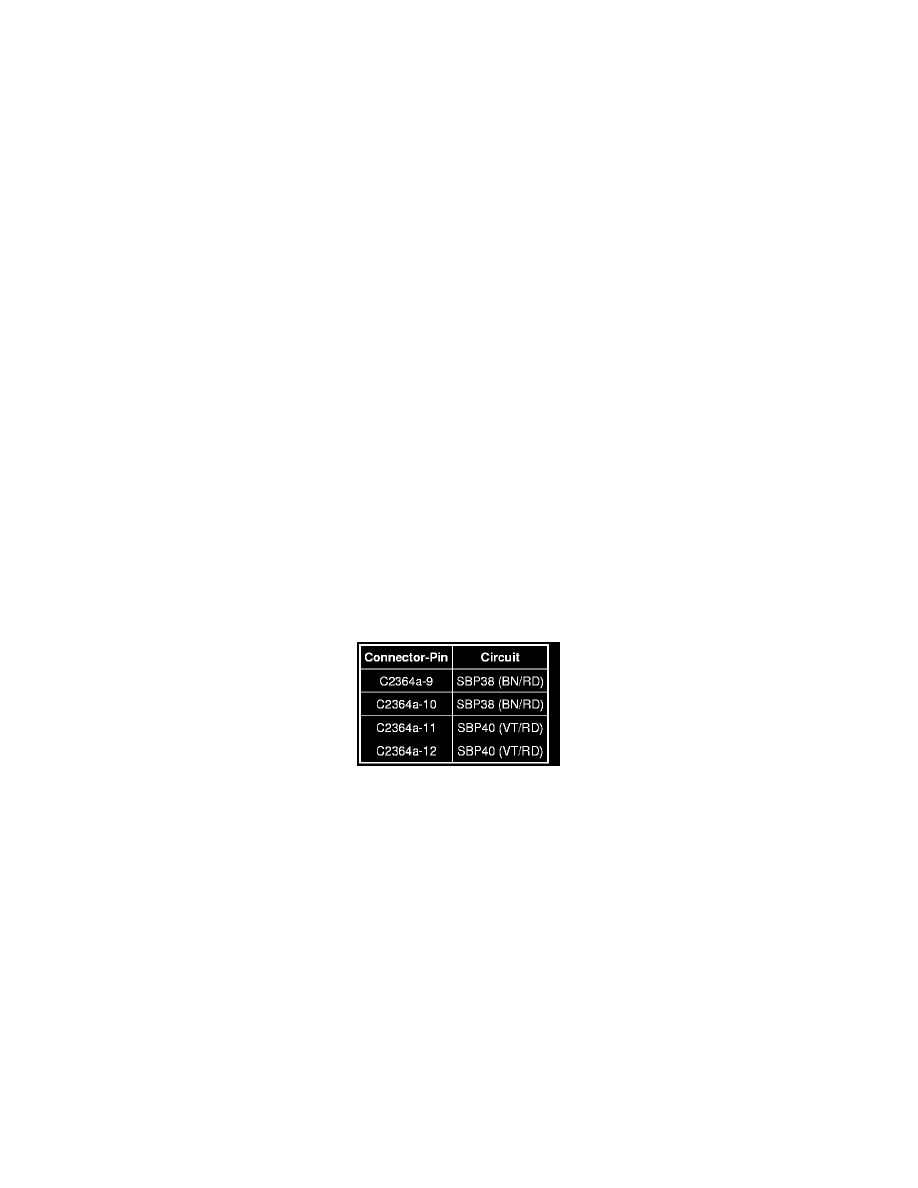
Measure the voltage between the audio DSP module, harness side and ground as follows:
-
Are the voltages greater than 10 volts?
Yes
GO to L2.
No
VERIFY the SJB fuse 38 (20A) or fuse 40 (20A) is OK. If OK, REPAIR the circuit in question. If not OK, REFER to the Wiring Diagrams to identify
the possible causes of the circuit short. CLEAR the DTCs. REPEAT the network test with the scan tool.
-------------------------------------------------
L2 CHECK THE AUDIO DSP MODULE GROUND CIRCUITS FOR AN OPEN
-
Ignition OFF.
-
Disconnect: Negative Battery Cable.
-
Measure the resistance between the audio DSP module, harness side and ground as follows: