
Expedition 2WD V8-5.4L (2009)
INSTALL a new PAM. CLEAR the DTCs. REPEAT the network test with the scan tool.
No
The system is operating correctly at this time. The concern may have been caused by a loose or corroded connector. CLEAR the DTCs. REPEAT the
network test with the scan tool.
-------------------------------------------------
Pinpoint Test T: The Accessory Protocol Interface Module (APIM) Does Not Respond To The Scan
Tool
Communications Network
Pinpoint Tests
Pinpoint Test T: The Accessory Protocol Interface Module (APIM) Does Not Respond To The Scan Tool
Refer to Wiring Diagram Set 14, Module Communications Network for schematic and connector information. See: Diagrams/Electrical
Diagrams/Diagrams By Number
Normal Operation
The Accessory Protocol Interface Module (APIM) communicates with the scan tool through the High Speed Controller Area Network (HS-CAN).
Circuits VDB04 (WH/BU) (HS-CAN +) and VDB05 (WH) (HS-CAN -) provide the HS-CAN connection to the APIM. Circuits VDB06 (GY/OG)
(MS-CAN +) and VDB07 (VT/OG) (MS-CAN -) provide the Medium Speed Controller Area Network (MS-CAN) connection to the APIM. Voltage for
the APIM is provided by circuit SBP03 (BU/RD). Circuit GD114 (BK/BU) provides ground.
This pinpoint test is intended to diagnose the following:
-
Fuse
-
Wiring, terminals or connectors
-
APIM
PINPOINT TEST T: THE APIM DOES NOT RESPOND TO THE SCAN TOOL
NOTICE: Use the correct probe adapter(s) when making measurements. Failure to use the correct probe adapter(s) may damage the
connector.
NOTE: Failure to disconnect the battery when instructed will result in false resistance readings. Refer to Battery.
-------------------------------------------------
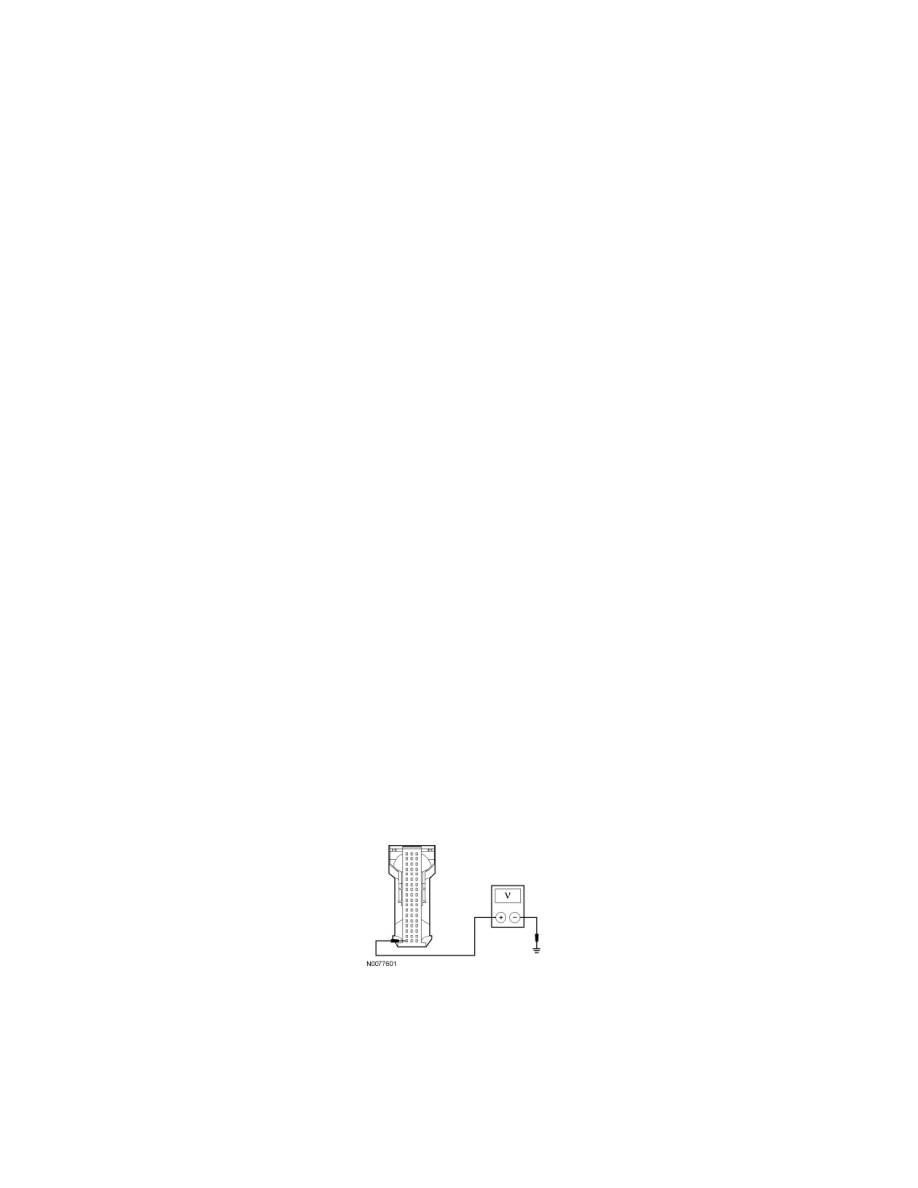
T1 CHECK THE APIM VOLTAGE SUPPLY CIRCUIT FOR AN OPEN
-
Disconnect: APIM C3342.
-
Ignition ON.
-
Measure the voltage between the APIM C3342-1, circuit SBP03 (BU/RD), harness side and ground.
-
Is the voltage greater than 10 volts?
Yes
GO to T2.
No
VERIFY the Smart Junction Box (SJB) fuse 3 (15A) is OK. If OK, REPAIR the circuit in question. If not OK, REFER to the Wiring Diagrams to