
F 150 4WD V8-4.6L VIN 8 (2010)
-
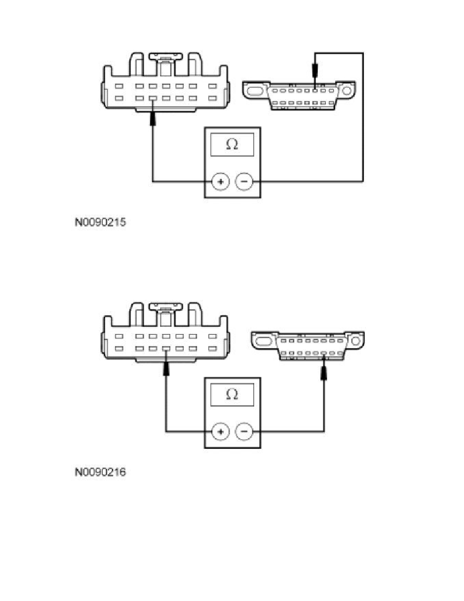
Measure the resistance between the TBC module C2142-11, circuit VDB05 (WH) or HSC2-A (WH), harness side and the DLC C251-14, circuit
VDB05 (WH), harness side.
-
Are the resistances less than 5 ohms?
Yes
CONNECT the negative battery cable. GO to G4.
No
REPAIR the circuit. CONNECT the negative battery cable. CLEAR the DTCs. REPEAT the network test with the scan tool.