
F 250 2WD Super Duty V8-5.4L (2008)
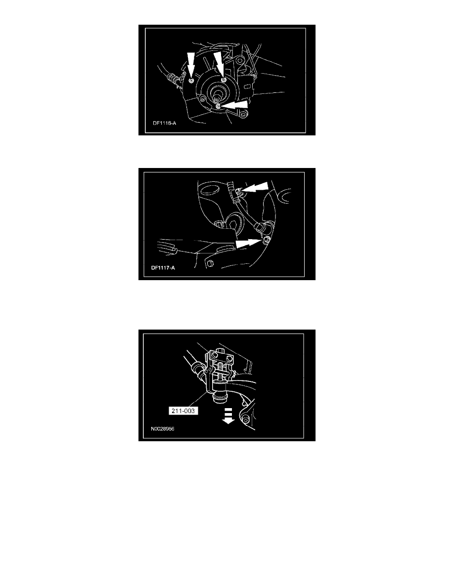
3. If equipped, remove the wheel speed sensor harness bolt, sensor bolt and the sensor.
^
To install, tighten to 8 Nm (71 inch lbs.).
4. Remove the cotter pin, nut retainer and the tie-rod end nut.
^
Discard the cotter pin.
^
To install, tighten to 115 Nm (85 ft. lbs.).
5. Using the special tool, disconnect the tie-rod end.
6. Remove the upper ball joint nut and bolt.
^
To install, tighten to 80 Nm (59 ft. lbs.).
7. CAUTION: Do not allow the camber adjustment sleeve to contact the ball joint seal when installing a sleeve, or damage to the ball joint
seal may occur. Allow for a minimum of 2 mm (0.079 inch) clearance between the camber adjustment sleeve and the ball joint seal.
Remove the camber adjustment sleeve.
8. CAUTION: To prevent damage to the ball joint seal and the ball joint socket, do not use a pickle fork-type remover to loosen the ball
joints.
Remove and discard the cotter pin, then loosen, but do not remove, the nut.
9. Strike the lower end of the front axle to free the ball joint from the axle.