| PINPOINT TEST A : HEADLAMP LEVELING INOPERATIVE/MALFUNCTIONING |
| TEST CONDITIONS | DETAILS/RESULTS/ACTIONS |
| A1: DETERMINE THE FAULT CONDITION |
| | 1 Determine the fault condition. |
| | Is the headlamp leveling defective in both headlamps? Yes No - Right-hand side inoperative: GO to A9. - Left or right-hand side malfunctioning: CHECK and if necessary RENEW the headlamp range adjustment unit. CHECK the operation of the system. |
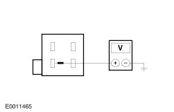
| A2: CHECK CONTROL CIRCUIT FOR SHORT TO BATTERY VOLTAGE |
| | 1 Ignition switch in position 0. |
| | 2 Disconnect headlamp adjust variable resistor from connector C68. |
| | 3 Disconnect left-hand headlamp from connector C157. |
| | 4 Disconnect right-hand headlamp from connector C174. |
| | 5 Ignition switch in position II. |
| | 6 Measure the voltage between the left-hand headlamp, connector C157, pin 5, circuit 63S-AC6 (WH), wiring harness side and ground. |
| | Does the meter display battery voltage? Yes LOCATE and RECTIFY the short to battery voltage in the circuits connected to soldered connection S915 using the Wiring Diagrams. No |
| A3: CHECK THE RIGHT-HAND HEADLAMP |
| | 1 Ignition switch in position 0. |
| | 2 Connect right-hand headlamp to connector C174. |
| | 3 Switch on the parking lights. |
| | 4 Measure the voltage between the left-hand headlamp, connector C157, pin 5, circuit 63S-AC6 (WH), wiring harness side and ground. |
| | Does the meter display battery voltage? Yes CHECK and if necessary RENEW the headlamp range adjustment unit. CHECK the operation of the system. No |
| A4: HEADLAMP ADJUST VARIABLE RESISTOR |
| | 1 Ignition switch in position 0. |
| | 2 Connect headlamp adjust variable resistor from connector C68. |
| | 3 Turn the variable resistor through the entire adjustment range during the measurement. |
| | 4 Measure the voltage between the left-hand headlamp, connector C157, pin 5, circuit 63S-AC6 (WH), wiring harness side and ground. |
| | Does the voltage vary with change of position of the variable resistor? Yes CHECK and if necessary RENEW the headlamp range adjustment unit in the left-hand headlamp. CHECK the operation of the system. No RENEW the headlamp adjust variable resistor. CHECK the operation of the system. |
| A5: CHECK VOLTAGE SUPPLY TO THE HEADLAMP ADJUST VARIABLE RESISTOR |
| | 1 Ignition switch in position 0. |
| | 2 Disconnect headlamp adjust variable resistor from connector C68. |
| | 3 Measure the voltage between the headlamp adjust variable resistor, connector C68, pin 1, circuit 29S- AC9 (OG)/29S-LA54 (OG), wiring harness side and ground. |
| | Does the meter display battery voltage? Yes No LOCATE and RECTIFY the break in the circuit between soldered connection S64 and variable resistor using the Wiring Diagrams. CHECK the operation of the system. |
| A6: CHECK CONTROL CIRCUIT FOR OPEN CIRCUIT |
| | 1 Disconnect left-hand headlamp from connector C157. |
| | 2 Disconnect right-hand headlamp from connector C174. |
| | 3 Using a fused test cable (7.5 A) at the variable resistor, bridge between connector C68, pin 1, circuit 29-AC9 (OG)/29S-LA54 (OG) and pin 2, circuit 63S-AC6 (WH), wiring harness side. |
| | 4 Ignition switch in position II. |
| | 5 Measure the voltage between the left-hand headlamp, connector C157, pin 5, circuit 63S-AC6 (WH), wiring harness side and ground. |
| | Does the meter display battery voltage? Yes RENEW the headlamp adjust variable resistor. CHECK the operation of the system. No LOCATE and RECTIFY the break in the circuit between the variable resistor and soldered connection S915 using the Wiring Diagrams. CHECK the operation of the system. |
| A7: CHECK CONTROL CIRCUIT FOR OPEN CIRCUIT |
| | 1 Ignition switch in position 0. |
| | 2 Disconnect left-hand headlamp from connector C157. |
| | 3 Ignition switch in position II. |
| | 4 Measure the resistance between the headlamp adjust variable resistor, connector C68, pin 2, circuit 63S-AC6 (WH), wiring harness side and left-hand headlamp, connector C157, pin 5, circuit 63S-AC6 (WH), wiring harness side. |
| | Is less than 2 Ohm measured? Yes No LOCATE and RECTIFY the break in the circuit between soldered connection S915 and the left-hand headlamp using the Wiring Diagrams. CHECK the operation of the system. |
| A8: CHECK CIRCUITS IN HEADLAMP FOR HEADLAMP RANGE ADJUSTMENT UNIT |
| | 1 Ignition switch in position 0. |
| | 2 Disconnect headlamp range adjustment unit in left-hand headlamp from connector C157a. |
| | 3 Measure the resistance between headlamp: - connector C157, pin 5, component side and headlamp range adjustment unit in headlamp, connector C157a, pin 2, circuit (BU), wiring harness side.
- connector C157, pin 2, component side and headlamp range adjustment unit in headlamp, connector C157a, pin 3, circuit (VT/YE), wiring harness side.
- connector C157, pin 7, component side and headlamp range adjustment unit in headlamp, connector C157a, pin 1, circuit (BK), wiring harness side.
|
| | Is a resistance of less than 2 Ohms measured for all three measurements? Yes RENEW headlamp range adjustment unit in headlamp. CHECK the operation of the system. No RECTIFY break in relevant circuit (BU), (VT/YE) or (BK) in headlamp. CHECK the operation of the system. |
| A9: CHECK CONTROL CIRCUIT FOR OPEN CIRCUIT |
| | 1 Ignition switch in position 0. |
| | 2 Disconnect right-hand headlamp from connector C174. |
| | 3 Ignition switch in position II. |
| | 4 Measure the resistance between the headlamp adjust variable resistor, connector C68, pin 2, circuit 63S-AC6 (WH), wiring harness side and right-hand headlamp, connector C174, pin 5, circuit 63S-AC7 (WH/RD), wiring harness side and ground. |
| | Is less than 2 Ohm measured? Yes No LOCATE and RECTIFY the break in the circuit between soldered connection S915 and the right-hand headlamp using the Wiring Diagrams. CHECK the operation of the system. |
| A10: CHECK CIRCUITS IN HEADLAMP FOR HEADLAMP RANGE ADJUSTMENT UNIT |
| | 1 Ignition switch in position 0. |
| | 2 Disconnect headlamp range adjustment unit in right-hand headlamp from connector C174a. |
| | 3 Measure the resistance between headlamp: - connector C174, pin 5, component side and headlamp range adjustment unit in headlamp, connector C174a, pin 2, circuit (BU), wiring harness side.
- connector C174, pin 2, component side and headlamp range adjustment unit in headlamp, connector C174a, pin 3, circuit (VT/YE), wiring harness side.
- connector C174, pin 7, component side and headlamp range adjustment unit in headlamp, connector C174a, pin 1, circuit (BK), wiring harness side.
|
| | Is a resistance of less than 2 Ohms measured for all three measurements? Yes RENEW headlamp range adjustment unit in headlamp. CHECK the operation of the system. No RECTIFY break in relevant circuit (BU), (VT/YE) or (BK) in headlamp. CHECK the operation of the system. |