| Removal and Installation Special Tool(s) | | Separator, ball joint 13-006 | | | Guide pins, subframe 15-097A | Removal All Vehicles | | -
Disconnect the battery ground cable. | | | -
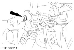
From inside the passenger compartment, remove the flexible coupling to pinion shaft pinch bolt. | | | -
From inside the passenger compartment, slacken the flexible coupling to column shaft pinch bolt. | | | -
Remove the exhaust manifold upper heat shields and remove the catalytic converter retaining nuts. For additional information, refer to Section 309-00 Exhaust System. | | | -
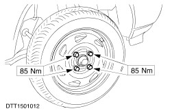
Slacken the wheel nuts, raise the vehicle and remove the front road wheels. | | | -
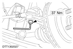
Remove the track rod end locknuts. - Hold the ball joint studs with an Allen key.
- Remove the locknuts.
| | | -
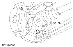
NOTE:When the track rod ends are separated from the spindle carriers the ball joint seals should be wrapped in cloth to protect them. Disconnect the track rod end ball joints from the spindle carriers. | Vehicles with manual transaxle | | -
Disconnect the gearshift linkage. | Vehicles with automatic transaxle | | -
Disconnect the gearshift linkage. - Unclip the linkage retaining clip.
- Remove the linkage retaining clip.
- Remove the cable retaining clip.
- Disengage the cable.
| All vehicles | | -
Remove the exhaust catalytic converter. For additional information, refer to Section 309-00 Exhaust System. | | | -
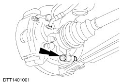
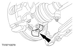
Remove the lower arm to spindle carrier pinch bolts and nuts. | | | -
Disconnect the lower arms from the spindle carriers. | | | -
Detach the connecting link from the suspension unit assembly. | | | -
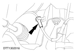
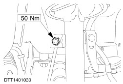
Remove the roll restrictor to transmission retaining bolt. | Vehicles with ABS braking system | | -
Unclip the ABS sensor cables from the crossmember. | All vehicles | | -
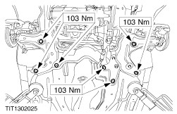
Support the crossmember assembly. | | | -
Remove the seven crossmember assembly retaining bolts. (Support removed for clarity). | | | -
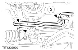
Lower the crossmember assembly enough to gain access to the power steering valve body pipes. | | | -
Remove the pinion shaft to body seal. | | | -
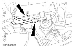
CAUTION:Whenever the steering gear unions are disconnected the steering gear must be plugged to prevent dirt ingress. Disconnect the power steering pipes from the steering gear valve body. - Disconnect the power steering pipes
- Allow the fluid to drain into a suitable container.
- Detach the power steeing pipes from the retaining bracket.
| | | -
Remove the crossmember assembly. | Installation All Vehicles | | -
Refit the components in the reverse order. | | | -
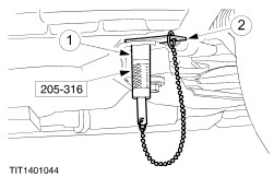
Align the crossmember. - Push the guide pins through the crossmember aligning holes.
- Slide the locking plates into the locking grooves and tighten the guide pin sleeves.
| | | -
Raise the crossmember engaging the guide pins into the alignment holes. | | | -
CAUTION:Make sure a heat shield is installed to prevent damage to the ball joint. Install the heat shield. | Vehicles with manual transaxle All vehicles | | -
CAUTION:Make sure the steering is in the straight ahead position. | |