| Removal and Installation Name Specification Super DOT 4 brake fluid ESD-M6C57-A Removal CAUTION:If brake fluid is spilt on the paintwork, the affected area must be immediately washed down with cold water. Left-hand drive vehicles | | -
Remove the brake master cylinder.
For additional information, refer to: Brake Master Cylinder - LHD (206-06 Hydraulic Brake Actuation, Removal and Installation).
| Right-hand drive vehicles | | -
Remove the battery tray.
For additional information, refer to: Battery Tray (414-01 Battery, Mounting and Cables, Removal and Installation).
| All vehicles | | -
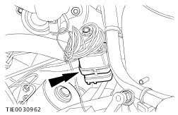
Detach the engine wiring harness electrical connector from the wheelhouse assembly. | | | -
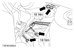
CAUTION:Cap the brake tubes to prevent fluid loss or dirt ingress. CAUTION:Plug the hydraulic control unit (HCU) ports to prevent fluid loss or dirt ingress. NOTE:Make a note of the position of the brake tubes, to aid installation. Remove the brake master cylinder to hydraulic control unit (HCU) brake tubes. | | | -
CAUTION:Cap the brake tubes to prevent fluid loss or dirt ingress. CAUTION:Plug the HCU ports to prevent fluid loss or dirt ingress. NOTE:Make a note of the position of the brake tubes, to aid installation. Disconnect the brake tubes from the HCU. | | | -
Detach the brake tubes from the bulkhead. | | | -
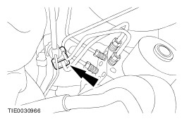
Disconnect the stability assist module electrical connector. | | | -
Raise and support the vehicle.
For additional information, refer to: Lifting (100-02 Jacking and Lifting, Description and Operation).
| | | -
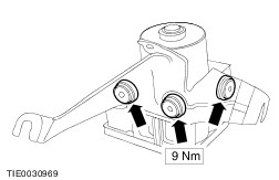
Remove the HCU and stability assist module support bracket lower retaining bolt. | | | -
Remove the HCU and stability assist module assembly and the support bracket. | | | -
Detach the HCU and stability assist module assembly from the support bracket. | | | -
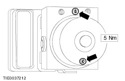
Remove the HCU to stability assist module retaining bolts. | Installation | | -
To install, reverse the removal procedure. | | | -
Bleed the brake system.
For additional information, refer to: Brake System Pressure Bleeding (206-00 Brake System - General Information, General Procedures).
| |