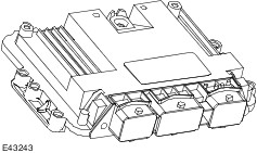
The PCM is located on a mounting bracket near the battery tray.
The PCM monitors and processes the input signals from the sensors and compares these with stored parameters.
Using this information, the PCM calculates the output signals for triggering the actuators.
A diagnostics check can be carried out on the PCM through the data link connector (DLC) using WDS.
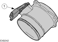
Intake air shutoff throttle
The intake air shutoff throttle is actuated by the PCM using pulse width modulation.
Depending on the driving situation, the volume air flow drawn in is varied in accordance with the position of the intake air shutoff throttle and thereby influences the composition of the recirculated exhaust gas.
Its other function is to make sure that the engine does not run on when it has been switched off.
EGR valve
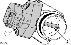
The MAF sensor is located on the outlet of the air filter housing and works in accordance with the hot wire principle.
The hot wire is located in the venturi of the MAF sensor and is electrically heated and is cooled by the intake air. The heating current is adjusted by the PCM so that the wire remains at a constant temperature. The mass of air flow can be calculated by this heating current which is supplied in the form of a reference voltage of between 11 volts and 14 volts.
The signal is used by the PCM to regulate the quantity of recirculated exhaust gas.
BPP switch
The BPP switch and the stoplamp switch are located on the pedal box and provide the PCM with the information that the brake pedal has been pressed and that the vehicle is therefore being decelerated.
The BPP switch is connected to the instrument cluster via a CAN bus. In its rest state the switch is closed and sends a ground signal to the PCM.
The signal from the BPP switch is used in the event of failure of the APP sensor for the emergency operating mode.
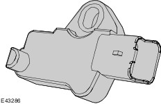
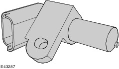
CKP sensor
The CKP sensor is attached to the oil pump housing, behind the crankshaft timing pulley.
The CKP sensor detects a magnetic disc with 58+2 magnetic pole pairs on it, arranged around the circumference.
The CKP sensor uses the Hall effect principle.
CMP sensor
The CMP sensor is located behind the camshaft pulley.
The CMP sensor is attached to the valve cover by means of a bolt through a slot in the sensor housing which allows for adjustment.
When carrying out installation work, make sure that the gap between the CMP sensor and exhaust camshaft pulley is correct.
The CMP sensor uses the Hall effect principle.
For detection of cylinder number 1, different sized windows have been milled into the exhaust camshaft timing pulley. During starting, the CKP sensor and the CMP sensor are synchronized. If both signals are present, the engine will be started. If the signal from the CMP sensor fails while the engine is running, the engine continues to run using the signals from the CKP sensor. If the CMP signal is missing at the next starting operation, it will not be possible to start the engine.
APP sensor
The APP sensor is a double contact-less inductive sensor.
For safety reasons, the APP sensor consists of two sensors.
If the APP sensor malfunctions when the vehicle is in operation, a diagnostic trouble code (DTC) will be stored in the PCM.
If one of the sensors of the APP sensor fails, the engine runs with reduced power.
If the APP sensor fails, the engine is regulated to a maximum engine speed of up to 1200 rev/min after a single operation of the BPP switch and the stop lamp switch and a subsequent comparative plausibility test. The vehicle can only be accelerated to a maximum speed of 56 km/h
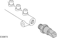
FRP sensor
The FRP sensor is located at the side on the fuel rail and measures the fuel pressure in the fuel rail.
The signal of the fuel pressure sensor is used by the PCM as in input variable for calculating the injected fuel quantity and the start of injection.
The fuel pressure sensor contains a piezoelectric element that sends a variable voltage signal to the PCM, as a function of fuel pressure.
Fuel temperature sensor