| PINPOINT TEST A : THE HORN IS INOPERATIVE |
| TEST CONDITIONS | DETAILS/RESULTS/ACTIONS |
| A1: CHECK THE HORN FOR POWER |
| | 1 Disconnect Horn C413 - All Except Vehicles with 2.0L Duratec-HE (MI4) engine or 1.6L Duratorq-TDCi (DV) Diesel engine. |
| | 2 Disconnect Horn C414 - Vehicles with 2.0L Duratec-HE (MI4) engine or 1.6L Duratorq-TDCi (DV) Diesel engine. |
| | 3 Measure the voltage between the horn C413 pin 1 or C414 pin 1, circuit 29S-GJ6 (OG/YE), harness side and ground while pressing the horn switch. |
| | Is the voltage greater than 10 volts? Yes All Except Vehicles with 2.0L Duratec-HE (MI4) engine or 1.6L Duratorq-TDCi (DV) Diesel engine, INSTALL a new horn. TEST the system for normal operation. Vehicles with 2.0L Duratec-HE (MI4) engine or 1.6L Duratorq-TDCi (DV) Diesel engine, GO to A2. No |
| A2: CHECK THE HORN GROUND CIRCUIT 31-GJ6 (BK) |
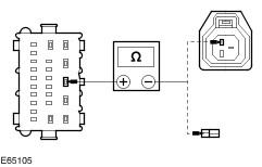
| | 1 Measure the resistance between the horn C414 pin 2, circuit 31-GJ6 (BK), harness side and ground. |
| | Is the resistance less than 5 ohms? Yes INSTALL a new horn. TEST the system for normal operation. No REPAIR the circuit. TEST the system for normal operation. |
| A3: CHECK CIRCUIT 29S-GJ6 (OG/YE) FOR OPEN CIRCUIT |
| | 1 Disconnect GEM C317. |
| | 2 Measure the resistance between the GEM C317 pin 3, circuit 29S-GJ6 (OG/YE), harness side and the horn C413 pin 1 or C414 pin 1, circuit 29S-GJ6 (OG/YE), harness side. |
| | Is the resistance less than 5 ohms? Yes No REPAIR the circuit. TEST the system for normal operation. |
| A4: CHECK THE GEM FOR POWER |
| | 1 Measure the voltage between the GEM C317 pin 4, circuit 29-GJ8 (OG), harness side and ground. |
| | Is the voltage greater than 10 volts? Yes No REPAIR circuit 29-GJ8 (OG). TEST the system for normal operation. |
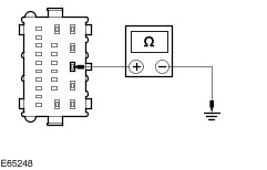
| A5: CHECK THE GEM GROUND CIRCUIT 31-DK20 (BK) |
| | 1 Disconnect GEM C318. |
| | 2 Measure the resistance between the GEM C318 pin 3, circuit 31-DK20 (BK), harness side and ground. |
| | Is the resistance less than 5 ohms? Yes No REPAIR the circuit. TEST the system for normal operation. |
| A6: CHECK THE HORN SWITCH CIRCUIT FOR OPEN |
| | 1 Disconnect GEM C320. |
| | 2 Measure the resistance between the GEM C320 pin 15, circuit 31S-GJ7 (BK/BU), harness side and ground while pressing the horn switch. |
| | Is the resistance less than 5 ohms? Yes INSTALL a new GEM.
REFER to: Generic Electronic Module (GEM) (419-10 Multifunction Electronic Modules, Removal and Installation).
TEST the system for normal operation. No |
| A7: CHECK THE HORN SWITCH GROUND CIRCUIT |
| | 1 Disconnect Clockspring C763 - Vehicles Without Stability Assist. |
| | 2 Disconnect Clockspring C353 - Vehicles With Stability Assist. |
| | 3 Measure the resistance between the clockspring C763 pin 7, circuit 31-GJ9 (BK) (vehicles without stability assist) or C353 pin 14, circuit 31-GJ9 (BK) (vehicles with stability assist), harness side and ground. |
| | Is the resistance less than 5 ohms? Yes No REPAIR circuit 31-GJ9 (BK). TEST the system for normal operation. |
| A8: CHECK CIRCUIT 31S-GJ7 (BK/BU) FOR OPEN CIRCUIT |
| | 1 Measure the resistance between the clockspring C763 pin 6, circuit 31S-GJ7 (BK/BU) (vehicles without stability assist) or C353 pin 13, circuit 31S-GJ7 (BK/BU) (vehicles with stability assist), harness side and the GEM C320 pin 15, circuit 31S-GJ7 (BK/BU), harness side. |
| | Is the resistance less than 5 ohms? Yes No REPAIR the circuit. TEST the system for normal operation. |
| A9: CHECK THE CLOCKSPRING CIRCUIT FOR OPEN CIRCUIT |
WARNING:To deactivate the driver air bag, refer to the procedure in section 501-20B for the correct air bag deactivation procedure. Failure to follow this instruction, may result in personal injury. |
| | 1 Remove the driver air bag module.
REFER to: Driver Air Bag Module (501-20B Supplemental Restraint System, Removal and Installation).
|
| | 2 Measure the resistance between the driver air bag connector, clockspring side and the clockspring C763 pin 6, circuit 31S-GJ7 (BK/BU) (vehicles without stability assist) or C353 pin 13, circuit 31S-GJ7 (BK/BU) (vehicles with stability assist) component side. |
| | Is the resistance less than 5 ohms? Yes No INSTALL a new clockspring.
REFER to: Clockspring (501-20B Supplemental Restraint System, Removal and Installation).
TEST the system for normal operation. |
| A10: CHECK THE CLOCKSPRING CIRCUIT FOR OPEN CIRCUIT |
| | 1 Measure the resistance between the driver air bag connector, clockspring side and clockspring C763 pin 7, circuit 31-GJ9 (BK) (vehicles without stability assist) or C353 pin 14, circuit 31-GJ9 (BK) (vehicles with stability assist) component side. |
| | Is the resistance less than 5 ohms? Yes No INSTALL a new clockspring.
REFER to: Clockspring (501-20B Supplemental Restraint System, Removal and Installation).
TEST the system for normal operation. |
| A11: CHECK THE HORN SWITCH CIRCUIT FOR OPEN CIRCUIT |
| | 1 Measure the resistance between the clockspring pin 6 and pin 7 (vehicles without stability assist) or pin 13 and pin 14 (vehicles with stability assist) component side while pressing the horn switch. |
| | Is the resistance less than 5 ohms? Yes INSTALL a new GEM.
REFER to: Generic Electronic Module (GEM) (419-10 Multifunction Electronic Modules, Removal and Installation).
TEST the system for normal operation. No INSTALL a driver air bag module.
REFER to: Driver Air Bag Module (501-20B Supplemental Restraint System, Removal and Installation).
TEST the system for normal operation. |