
Flex AWD V6-3.5L (2009)
-
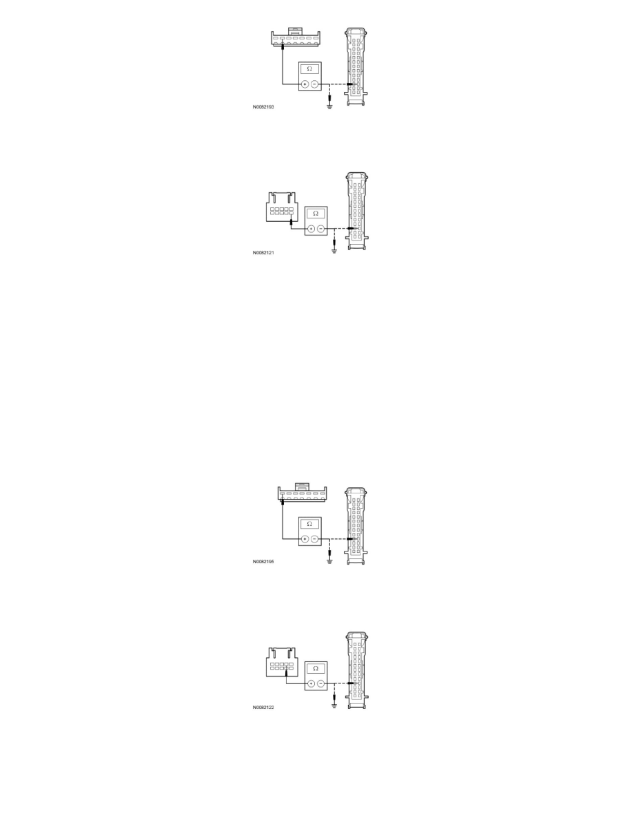
For vehicles with the SYNC system, measure the resistance between the auto-dimming interior mirror C9012-6, circuit VMC31 (GY/BU), harness
side and the IC C220-16, circuit VMC31 (GY/BU), harness side; and between the auto-dimming interior mirror C9012-6, circuit VMC31
(GY/BU), harness side and ground.
-
Is the resistance less than 5 ohms between the auto-dimming interior mirror and the IC, and greater than 10,000 ohms between the
auto-dimming interior mirror and ground?
Yes
GO to A5.
No
REPAIR the circuit. CLEAR the DTCs. REPEAT the self-test.
-------------------------------------------------
A5 CHECK CIRCUIT VMC30 (BU/GY) FOR AN OPEN OR SHORT TO GROUND
-
For vehicles without the SYNC system, measure the resistance between the auto-dimming interior mirror C911-7, circuit VMC30 (BU/GY),
harness side and the IC C220-17, circuit VMC30 (BU/GY), harness side; and between the auto-dimming interior mirror C911-7, circuit VMC30
(BU/GY), harness side and ground.
-
For vehicles with the SYNC system, measure the resistance between the auto-dimming interior mirror C9012-2, circuit VMC30 (BU/GY), harness
side and the IC C220-17, circuit VMC30 (BU/GY), harness side; and between the auto-dimming interior mirror C9012-2, circuit VMC30
(BU/GY), harness side and ground.
-
Is the resistance less than 5 ohms between the auto-dimming interior mirror and the IC, and greater than 10,000 ohms between the
auto-dimming interior mirror and ground?
Yes
GO to A6.