
Flex FWD V6-3.5L (2010)
-
Is the voltage greater than 10 volts?
Yes
GO to I2.
No
VERIFY the Smart Junction Box (SJB) fuse 35 (10A) is OK. If OK, REPAIR the circuit. If not OK, REFER to the Wiring Diagrams to identify the
possible causes of the circuit short. TEST the system for normal operation. See: Diagrams/Electrical Diagrams/Diagrams By Number
-------------------------------------------------
I2 CHECK THE PAM GROUND CIRCUIT FOR AN OPEN
-
Ignition OFF.
-
Disconnect: Negative Battery Cable.
-
Measure the resistance between the PAM C3267-4, circuit GD145 (BK/BU), harness side and ground.
-
Is the resistance less than 5 ohms?
Yes
GO to I3.
No
REPAIR the circuit. CONNECT the negative battery cable. TEST the system for normal operation.
-------------------------------------------------
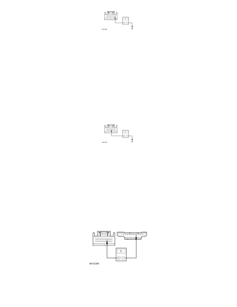
I3 CHECK THE HS-CAN CIRCUITS BETWEEN THE PAM AND THE DLC FOR AN OPEN
-
Measure the resistance between the PAM C3267-3, circuit VDB04 (WH/BU), harness side and the Data Link Connector (DLC) C251-6, circuit
VDB04 (WH/BU), harness side.
-
Measure the resistance between the PAM C3267-11, circuit VDB05 (WH), harness side and the DLC C251-14, circuit VDB05 (WH), harness
side.