| Disassembly and Assembly Special Tool(s) | | Gaiter clamp tightening tool 204-169 (14-044) | | | Separating tool, Bearing/Gear 205-310 (15-091) | | | Remover, Bearing/Gear 205-311 (15-092) | | | Installer, Extension Housing Bushing/Oil Seal 308-046 (16-016) | Materials Name Specification Constant velocity joint high-temperature grease ESP-M1C207-A Disassembly | | -
CAUTION: Use a vice with protective jaw covers. Detach the inner constant velocity joint from the front halfshaft. - Clamp the front halfshaft in a vice.
- Separate and discard the clamping straps. Slide the boot back.
- Remove the tripode housing.
- Remove the grease from inside the joint.
| | | -
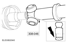
Using the special tools detach the tripode star. - Remove and discard the rubber boot.
| | | -
Detach the outer CV joint boot. - Separate and discard the clamping straps.
- Remove and discard the rubber boot.
| Assembly | | -
NOTE: Install a new rubber boot. Install the outer CV joint boot. - Pack the CV joint with grease.
For additional information, refer to: Technische Daten (205-04 Vorderradantriebswellen, Specifications).
- Press the rubber boot into the groove of the CV joint.
- Insert a small screwdriver under the boot seat to allow the air to escape.
- Position the rubber boot.
| | | -
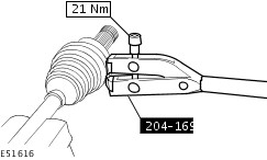
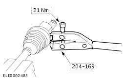
Insert the small and large clamping straps in the boot ring grooves and tighten them with the special tool. | | | -
NOTE: Install a new clamping strap. NOTE: Install a new rubber boot. Place the clamping strap and inner CV joint rubber boot in position on the front halfshaft. | | | -
Attach the inner CV joint boot. - Insert the clamping strap in the boot ring groove and tighten with the special tool.
| | | -
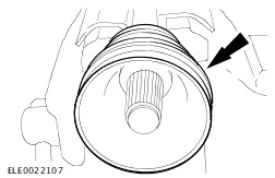
CAUTION: Do not damage the universal joint rollers. NOTE: Chamfer points towards the front halfshaft. Install the tripode star. - Using the special tool, push the tripode star onto the front halfshaft to the stop.
| | | -
NOTE: Install a new snap ring. Install the snap-ring. | | | -
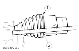
Fill the constant velocity joint with grease. For additional information, refer to: Technische Daten (205-04 Vorderradantriebswellen, Specifications). - Insert a small screwdriver under the boot seat to allow the air to escape.
- Push on the CV joint to stop, then pull it back 20 mm.
| | | -
NOTE: Install a new clamping strap. Insert the clamping strap in the boot ring groove and tighten with the special tool. | | |