| Removal and Installation Worldwide Diagnostic System (WDS) Removal NOTE:If a new PCM is being installed connect WDS. Upload the PCM configuration information using the programmable modules installation routine prior to commencing the removal of the PCM. All vehicles | | -
Disconnect the battery ground cable.
For additional information, refer to: Battery Disconnect (414-01 Battery, Mounting and Cables, General Procedures).
| | | -
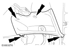
Remove the instrument panel side trim. | | | -
Remove the cowl side trim panel. | Right–hand drive vehicles | | -
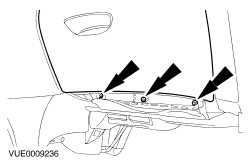
Remove the instrument panel lower panel. - Disconnect the data link connector electrical connector.
| Left–hand drive vehicles | | -
Remove the instrument panel lower trim panel. | Vehicles built up to 10/2001 | | -
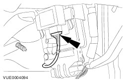
Disconnect the central security module (CSM) electrical connector. | | | -
Detach the PCM securing bracket. | Vehicles built 10/2001 onwards | | -
Detach the generic electronic module (GEM) module from the PCM and position it to one side. | | | -
Detach the PCM from the retaining bracket. | All Vehicles | | -
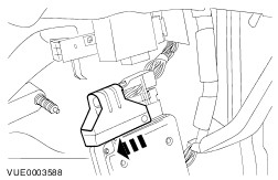
CAUTION:Make sure the floor covering is protected before drilling is started. Failure to follow this instruction may result in damage to the floor covering. Drill a 3mm pilot hole in the centre of the welded nut. | | | -
Drill a 8mm hole in the welded nut to release the shear bolt. - Remove and discard the shear bolt.
| | | -
Remove and discard the PCM security bracket. | | | -
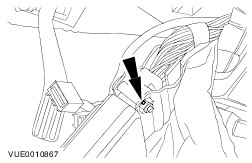
Disconnect the PCM electrical connector. | Installation All vehicles | | -
Connect the PCM electrical connector. | | | -
NOTE:Install a new PCM security bracket. Install the PCM security bracket. | | | -
NOTE:Install a new PCM security bracket shear bolt. Install the PCM security bracket shear bolt. | Vehicles built up to 10/2001 | | -
Attach the PCM securing bracket. | | | -
Connect the CSM electrical connector. | Vehicles built 10/2001 onwards | | -
Attach the GEM module to the PCM. | | | -
Attach the PCM to the retaining bracket. | Left–hand drive vehicles | | -
Install the instrument panel lower trim panel. | Right–hand drive vehicles | | -
Install the instrument panel lower panel. - Connect the data link connector electrical connector.
| All vehicles | | -
Install the cowl side trim panel. | | | -
Install the instrument panel side trim. | | | -
Connect the battery ground cable.
For additional information, refer to: Battery Disconnect (414-01 Battery, Mounting and Cables, General Procedures).
| NOTE:If a new PCM is being installed connect WDS. Download the PCM configuration information using the programmable modules installation routine after the installation of the PCM. | | -
Initialize the door window motors.
For additional information, refer to: Door Window Motor Initialization (501-11 Glass, Frames and Mechanisms, General Procedures).
| |