Refer to Wiring Diagrams Section 413-01, for schematic and connector information.
Worldwide Diagnostic System (WDS)
Principles of Operation
This instrument cluster is called the hybrid electronic instrument cluster (HEC) because it has a mix of intelligent and hardwired electrical signals. The instrument cluster has a built-in self-test and a Standard Corporate Protocol (SCP) link to the Powertrain Control Module (PCM). This allows the instrument cluster and the PCM to communicate with each other. The instrument cluster consists of gauges, indicators and warning indicators.
When the ignition switch is in the ON position with the engine off the instrument cluster carries out a display test to verify that the warning/indicator lamps and monitored systems are functioning correctly. The warning indicators that illuminate during this display test are:
- Anti-lock brake system (ABS) (if fitted)
- Air bag system
- Passenger air bag deactivate switch
- Charging system
- Brake warning indicator
- Low fuel indicator (if fitted)
- Low oil pressure
- Malfunction indicator lamp (MIL)
- Powertrain check indicator lamp
- Traction control (if fitted)
- Overdrive (if fitted)
- Shift up (if fitted)
- Glow plugs (if fitted)
Hybrid Electronic Instrument Cluster (HEC) Gauges
Engine Temperature Gauge
Cylinder head temperature information is received by the PCM, from the engine coolant temperature (ECT) sensor or the cylinder head temperature (CHT) sensor. The instrument cluster receives engine temperature information from the PCM which is then used by the gauge. If the engine coolant temperature signal is missing or invalid, the instrument cluster will move the temperature gauge pointer to below the cold position.
Fuel Gauge
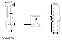
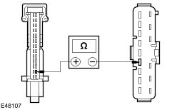
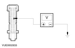
The instrument cluster receives the fuel level information from the fuel sender unit (part of the fuel pump module). This is a variable resistor which varies the ground supply to the gauge. When the fuel level is low, the resistance is low, when the fuel level is high the resistance is high. Incorporated into the instrument cluster is a low fuel warning indicator which illuminates when the fuel drops to a pre-determined level. If a faulty input signal is received the fuel gauge will then default to below the empty position and the low fuel warning indicator will illuminate. The fuel level input signal is heavily dampened to allow for movement of fuel in the tank when the ignition is in the ON position. The fuel gauge pointer will be moved to zero when the ignition is turned off.
Speedometer
Vehicle speed information is received by the PCM from the vehicle speed sensor (VSS). The PCM compensates for tire size and inputs vehicle speed information to the instrument cluster, which is then indicated in km/h or mph at the gauge. If this information is missing the instrument cluster defaults the speedometer to zero.
Odometer
Distance traveled information is received by the PCM, from the VSS. The PCM compensates for tyre size and inputs the distance travelled to the instrument cluster which, electronically displays this information in an LCD display. If this information is not received the LCD will display dashes. Also incorporated on this LCD is a tripmeter which is reset by using the reset button.
Tachometer
The instrument cluster receives tachometer information from the PCM. If the engine speed (RPM) information sent to the instrument cluster is invalid or missing, the instrument cluster will default the tachometer to zero.
Warning Indicators
Air Bag Warning Indicators
The air bag warning indicators are controlled by the air bag module.
REFER to: Air Bag and Safety Belt Pretensioner Supplemental Restraint System (SRS) - Vehicles Built Up To: 10/2001 (501-20B Supplemental Restraint System, Diagnosis and Testing).
ABS Warning Indicator
The instrument cluster anti-lock brake system warning (ABS) indicator is hardwired directly to the ABS module. An open circuit, a short to battery, or an ABS failure will illuminate the ABS warning indicator.
REFER to: Anti-Lock Control (206-09A Anti-Lock Control, Diagnosis and Testing).
Warning indicator must be enabled, see Configuration of instrument cluster.
Brake System Warning Indicator
The brake system warning indicator has multiple functions. The brake system warning indicator self-tests the system when the ignition switch is in the engine RUN position by grounding the circuit. The warning indicator illuminates if the brake fluid is low or if the parking brake is set. If both the ABS warning indicator and the brake system warning indicators are illuminated, an EBD concern exists.
REFER to: Anti-Lock Control (206-09A Anti-Lock Control, Diagnosis and Testing).
Charging System Warning Indicator
The PCM controls the charging system and the charging system warning indicator. The PCM is therefore responsible for turning the lamp off once the system is running, and illuminating it under fault conditions (including stall conditions).
REFER to: Charging System (414-00 Charging System - General Information, Diagnosis and Testing).
The High Beam Indicator
The high beam indicator is hardwired directly to the multifunction switch.
Left and Right Turn Signal Indicators
The left and right turn signal indicators are hardwired directly to the multifunction switch.
Malfunction Indicator Lamp (MIL)
The malfunction indicator lamp (MIL) illuminates when a diagnostic trouble code (DTC) is registered in the PCM if the fault affects exhaust emissions. This lamp can only be extinguished by using WDS after the fault has been rectified and the DTC cleared from the PCM.
Powertrain Check Indicator Lamp
The powertrain check indicator lamp illuminates when a DTC is registered in the PCM which does not affect exhaust emissions. This lamp will also illuminate if fail-safe cooling strategy is invoked by the PCM.
REFER to: Engine Cooling (303-03 Engine Cooling, Diagnosis and Testing).
Traction Control (TC) Indicator
The traction control (TC) indicator is controlled by the ABS/TC module. The TC indicator is illuminated when the TC is active. Traction control can be disabled by depressing the TC OFF button.
REFER to: Anti-Lock Control - Traction Control (206-09B Anti-Lock Control - Traction Control, Diagnosis and Testing).
Low Oil Pressure Warning Indicator
The low oil pressure warning indicator is hardwired to the engine low oil pressure switch. With the ignition switch in position II, the low oil pressure indicator illuminates. After the engine is started and the oil pressure builds up, the oil pressure switch opens and switches off the oil pressure warning indicator.
Low Fuel Warning Indicator
This indicator must be enabled, see Configuration of instrument cluster.
Door ajar indicator
The door ajar indicator is controlled by the central security module (CSM) and the door, liftgate or luggage compartment lid switches. The system operates by supplying a ground when a door or liftgate is opened or not fully closed, which will illuminate the indicator.
Tailgate Release Inhibit
The instrument cluster uses vehicle speed information from the PCM to provide a tailgate release inhibit signal to the central security module (CSM). Tailgate release is only enabled with the ignition in position 0.
Standard Corporate Protocol.
The standard corporate protocol (SCP) is an electronic link enabling the instrument cluster to communicate with the PCM, therefore creating a pathway for WDS to access the instrument cluster control systems. This increases the WDS diagnostic capabilities.
Configuration of Instrument Cluster
NOTE:All new instrument clusters will illuminate all of the warning indicators until it is configured using WDS.
The instrument cluster is a programmable module, which must be configured by selecting the Programmable Module Installation Routine on WDS.
On Board Computer
This computer is mounted in the message and information center.
REFER to: Information and Message Center (413-08 Information and Message Center, Diagnosis and Testing).
The on board computer can supply the driver with the following information.
- Trip information
- Ambient temperature
- Average speed
- Distance to empty
- Average fuel economy
Inspection and Verification
- Verify the customer concern by operating the system.
- Visually inspect for obvious signs of mechanical or electrical damage.
Visual Inspection Chart