| PINPOINT TEST B : THE HORN DOES NOT SOUND |
| TEST CONDITIONS | DETAILS/RESULTS/ACTIONS |
| B1: CHECK FUSE 7 (40A) |
| | 1 CHECK Fuse 7 (40A) Central Junction Box. |
| | Is the Audio Unit operating correctly? Yes No INSTALL a new fuse 7. TEST the system for normal operation. |
| B2: CHECK FUSE 34 (20A) |
| | 1 CHECK Fuse 33 (20A) Central Junction Box. |
| | Is the fuse OK? Yes No INSTALL a new fuse 33. TEST the system for normal operation. |
| B3: CHECK THE HORN RELAY |
| | 1 Disconnect Horn Relay K33. |
| | 2 Perform the relay component test. |
| | Is the relay OK? Yes No INSTALL a new Horn relay. TEST the system for normal operation. |
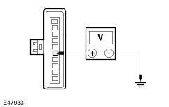
| B4: CHECK POWER TO THE CJB |
| | 1 Measure the voltage between the Horn relay C1023 pin 1, harness side and ground, and the Horn relay C1023 pin 3, harness side and ground. |
| | Are the voltages greater than 10 volts? Yes Vehicles with stabilty assist, GO to B5. Vehicles without stabilty assist, GO to B8. No REPAIR circuit 30-DA1 (RD). TEST the system for normal operation. |
| B5: CHECK POWER TO HORN SWITCH |
| | 1 Connect Horn Relay K33. |
| | 2 Remove the air-bag.
REFER to: Driver Air Bag Module (501-20B Supplemental Restraint System, Removal and Installation).
|
| | 3 Disconnect Clockspring C896. |
| | 4 Remove the steering column lower shroud. |
| | 5 Measure the voltage between the clockspring C896 pin 6, circuit 91S-GJ7 (BK/BU), harness side and ground. |
| | Is the voltage greater than 10 volts? Yes No REPAIR circuit 91S-GJ7 (BK/BU), TEST the system for normal operation. |
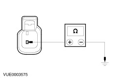
| B6: CHECK HORN SWITCH GROUND CIRCUIT |
| | 1 Measure the resistance between the clockspring C896 pin 7, circuit 91-PG30 (BK/WH), harness side and ground. |
| | Is the resistance less than 1 ohm? Yes No REPAIR circuit 91-PG30 (BK/WH), TEST the system for normal operation. |
| B7: CHECK OPERATION OF CLOCKSPRING |
| | 1 Measure the resistance between the clockspring component side C896 pin 6 and pin 7. Take note of the reading with the switch pressed as well as with the switch released. |
| | Is the resistance greater than 10,000 ohms (open circuit) with the switch released and less than 1 ohm with the switch pressed? Yes No |
| B8: CHECK POWER TO HORN SWITCH |
| | 1 Connect Horn Relay K33. |
| | WARNING:For correct deactivation procedure of air-bag, refer to procedure in Section 501-20B. 2 Remove the air-bag.
REFER to: Driver Air Bag Module (501-20B Supplemental Restraint System, Removal and Installation).
|
| | 3 Disconnect Clockspring C898. |
| | 4 Remove the steering column lower shroud. |
| | 5 Measure the voltage between the clockspring C898 pin 13, circuit 91S-GJ7 (BK/BU), harness side and ground. |
| | Is the voltage greater than 10 volts? Yes No REPAIR circuit 91S-GJ7 (BK/BU), TEST the system for normal operation. |
| B9: CHECK HORN SWITCH GROUND CIRCUIT |
| | 1 Measure the resistance between the clockspring C898 pin 14, circuit 91-PG30 (BK/WH), harness side and ground. |
| | Is the resistance less than 1 ohm? Yes No REPAIR circuit 91-PG30 (BK/WH), TEST the system for normal operation. |
| B10: CHECK OPERATION OF AIR-BAG SLIDING CONTACT |
| | 1 Measure the resistance between the clockspring component side C898 pin 13 and pin 14. Take note of the reading with the switch pressed as well as with the switch released. |
| | Is the resistance greater than 10,000 ohms (open circuit) with the switch released and less than 1 ohm with the switch pressed? Yes No |
| B11: CHECK HORN SWITCH |
| | 1 Disconnect Horn Switch C920. |
| | 2 Measure the resistance between the horn switch C920 pin 1 and pin 2. Take note of the reading with the switch pressed as well as with the switch released. |
| | Is the resistance greater than 10,000 ohms (open circuit) with the switch released and less than 1 ohm with the switch pressed? Yes Install a new air-bag sliding contact. TEST the system for normal operation. No INSTALL new horn switch(es). TEST the system for normal operation. |
| B12: CHECK POWER TO THE HORN |
| | 1 Connect Clockspring C896 or C898. |
| | 2 Connect Horn Switch C920. |
| | 3 Disconnect Horn C77. |
| | 4 Measure the voltage at horn C77 pin 1, circuit 29S-GJ1 (OG/BU), harness side and ground, whilst depressing the horn switch. |
| | Is the voltage greater than 10 volts? Yes No REPAIR circuit 29S-GJ1 (OG/WH). TEST the system for normal operation. |
| B13: CHECK GROUND CIRCUIT TO HORN |
| | 1 Measure the resistance between Horn C77 pin 2 circuit 31-GJ1 (BK), harness side and ground. |
| | Is the resistance less than 1 ohm? Yes INSTALL new horn. TEST the system for normal operation. No REPAIR circuit 31-GJ1 (BK). TEST the system for normal operation. |
| B14: CHECK POWER TO THE HORN(S) |
| | 1 Connect Clockspring C896 or C898. |
| | 2 Connect Horn Switch C920. |
| | 3 Disconnect Horn C982 or C981. |
| | 4 Measure the voltage at Horn(s) C982 pin 1, circuit 29S-GJ6 (OG/YE), harness side and ground; and C981 pin 1, circuit 29S-GJ10 (OG/GN), harness side and ground, whilst depressing the horn switch. |
| | Are the voltages greater than 10 volts? Yes No REPAIR circuit 29S-GJ6 (OG/YE) or 29S-GJ10 (OG/GN) as necessary. TEST the system for normal operation. |
| B15: CHECK GROUND CIRCUIT TO HORN(S) |
| | 1 Measure the resistance between the horn(s) C982 pin 2, circuit 31-GJ6 (BK), harness side and ground; and C981 pin 2, circuit 31-GJ10 (BK), harness side and ground. |
| | Are the resistances less than 1 ohm? Yes INSTALL new Horn(s) as necessary. TEST the system for normal operation. No REPAIR circuit 31-GJ6 (BK) or circuit 31-GJ10 (BK) as necessary. TEST the system for normal operation. |